Globally‑leading Supplier of Industrial Equipment
Providing industrial robots, flaw‑detection instruments, DIC equipment, information technology services and more for over 20 countries and regions worldwide
Corporate Advantages
Featured Products
Discover our most popular industrial machinery solutions

The HS-series industrial manipulator systems
1 Product Overview The HS-series industrial robotic arm system is designed for industrial automated production lines, delivering a combination of precision, stability, and versatility as an intelligent operation solution. Its flagship models are the HS-RA100, HS-RA300, and HS-RA500. Built on a modular structure and driven by high-performance servo drive units and intelligent motion control algorithms, the system offers accurate positioning, fast cycle times, a wide payload range, and easy interfacing with peripheral equipment, and is capable of performing six mainstream industrial operations: palletizing, welding, spray painting, assembly, cutting, and inspection and sorting. The three models correspond to the light, medium, and heavy payload classes respectively, allowing free model selection based on production line conditions, precision requirements, and working radius. Served industries include machinery manufacturing, automotive and auto parts, hardware processing, electronics and electrical equipment, chemical and building materials, and logistics and warehousing. With 24-hour continuous operation capability, the robotic arms take over repetitive, high-intensity, high-risk, and high-precision tasks from manual labor, thereby reducing labor costs, improving output efficiency, and ensuring consistent processing results across batches, in support of the automation and intelligence upgrade of production lines. In addition, the series adopts a standardized maintenance structure and built-in intelligent self-diagnostics, offering easy maintenance, low failure rates, and a long service life, with outstanding industrial application value. 2 Product Models and Core Specifications The HS-RA100, HS-RA300, and HS-RA500 belong to the same series and share consistent structure, control system, and adaptable operating scenarios. Their differences are primarily reflected in hardware indicators such as payload, working radius, and motion speed, facilitating model selection according to specific operating conditions. Detailed technical specifications for each model are shown in the table below: Technical Specification HS-RA100 HS-RA300 HS-RA500 Maximum rated payload 10 kg 30 kg 50 kg Maximum working radius 1200 mm 1800 mm 2200 mm Repeat positioning accuracy ±0.03 mm ±0.05 mm ±0.08 mm Degrees of freedom 6 axes 6 axes 6 axes Maximum motion speed (end effector) 6.5 m/s 5.8 m/s 5.2 m/s Drive method All-servo motor drive All-servo motor drive All-servo motor drive Control system HS Intelligent CNC System HS Intelligent CNC System HS Intelligent CNC System Operating temperature 0°C–45°C 0°C–45°C 0°C–45°C Protection rating IP65 IP65 IP65 Rated power 2.2 kW 3.8 kW 5.5 kW Machine weight 185 kg 320 kg 480 kg Mounting method Floor / wall / inverted Floor / wall / inverted Floor / wall / inverted Applicable operating scenarios Welding of small workpieces; spray painting; precision assembly; inspection and sorting of small parts; palletizing of light materials; cutting of small workpieces Welding of medium workpieces; full-surface spray painting; general assembly; routine inspection and sorting; palletizing of medium materials; cutting of regular workpieces Palletizing of heavy materials; welding of large workpieces; spray painting of large parts; assembly of heavy components; inspection of large parts; cutting of thick materials 3 Core Application Scenarios 3.1 Palletizing Application Scenario Scene background: Palletizing sits at the junction between production and warehousing logistics and is a critical link, commonly found in industries such as food and beverage, chemical, building materials, home appliances, and logistics and warehousing. It handles the stacking, transfer, inbound, and outbound of finished products, semi-finished goods, and raw materials. The traditional labor-intensive palletizing method presents several significant problems. First, it is physically demanding: repeated bending and lifting movements put employees at risk of lumbar strain and joint injuries, making positions difficult to retain and recruit for. Second, stacking quality varies from person to person, with skewed stacks, collapsing goods, and inconsistent layer counts occurring from time to time, which lowers warehouse space utilization and weakens transport safety. Third, manual cycle times cannot keep pace with the high-speed output of modern production lines, labor costs keep rising year after year, and cargo damage and rework caused by mishandling continue to add operational burdens. In addition, chemical and building materials often carry dust or slight corrosiveness, and long-term exposure is detrimental to worker health. Therefore, using automated equipment to achieve standardized palletizing has become a common industry requirement. Uniform stack patterns, controlled layer counts, and stable cycle times facilitate full utilization of warehouse space and enable convenient forklift transfer and inbound/outbound management. Equipment application process: The three models can be selected according to the weight and size of the materials, allowing the palletizing process to be completed automatically. Before production, technicians preconfigure palletizing trajectories, stacking layers, stack parameters, and gripping spacing in the HS Intelligent CNC System, adapting them to different material forms such as cartons, bags, drums, and cases. After materials are delivered by the conveyor line to the designated pickup station, the robotic arm performs positioning with the pneumatic gripper or vacuum suction fixture installed at the end effector, then executes gripping, lifting, and translation, placing materials smoothly onto pallets or warehouse racks at the target position according to the preset program. In terms of division of labor, the HS-RA100 targets light materials under 10 kg, such as snacks, small accessories, and lightweight cartons; the HS-RA300 handles medium materials of 30 kg, such as grain and oil products, medium-sized chemical bags, and home appliance accessories; and the HS-RA500 handles heavy materials of 50 kg, such as building material panels, large drum raw materials, and full heavy cases. During operation, the onboard intelligent sensing system continuously detects material position deviations and automatically fine-tunes the motion trajectory, compensating for pickup errors caused by conveyor line offset. The entire process requires no manual intervention and can continuously perform stacking, pallet replacement, and empty-pallet exchange cycles, meeting the needs of 24-hour continuous production on the line. Equipment maintenance advantages: Under palletizing conditions, the series excels in ease of maintenance and operational stability. The fully enclosed dustproof structure, with an IP65 protection rating, prevents dust and debris in warehouses and workshops from intruding, reducing common faults caused by accumulated dust such as jamming or sensor malfunction. The core transmission components are made of high-strength alloy materials that are wear-resistant and durable, capable of withstanding high-frequency, high-load reciprocating motion with significantly slowed wear. The onboard intelligent self-diagnostic system continuously monitors parameters such as motor temperature, operating load, trajectory deviation, and gripper status, issuing automatic warnings and storing fault codes at the first sign of minor abnormalities, enabling maintenance personnel to quickly locate and resolve issues and preventing minor problems from accumulating into downtime incidents. The equipment also adopts a modular disassembly approach: grippers, servo motors, transmission bearings, and other wear parts can be replaced individually without disassembling the entire machine, reducing maintenance time and cost. Compared with manual palletizing and general palletizing equipment, the HS-series robotic arms have fewer faults and longer service lives, with an average annual maintenance investment of less than 10% of manual labor wages, and require no frequent downtime for maintenance, maximizing continuous production line operation. 3.2 Welding Application Scenario Scene background: Welding is a fundamental process in industries such as machinery manufacturing, automotive and auto parts, hardware steel structures, and engineering machinery. It encompasses various processes including spot welding, arc welding, laser welding, and gas-shielded welding, and mainly completes the splicing, fixing, and forming of metal workpieces. The drawbacks and safety risks of manual welding are both prominent. Operations involve intense light, high temperatures, fumes, and arc radiation; long-term exposure can damage the operator's eyesight, respiratory system, and skin, making it a high-risk specialty post. Weld quality depends on the skill level and real-time condition of the welder, making it difficult to maintain consistent weld width, penetration depth, and spot uniformity. Defects such as cold welds, missed welds, weld beads, and deformation are common, and the qualification rate fluctuates considerably. Meanwhile, experienced welders are scarce and highly paid, and manual speed is limited, making it difficult to support high-volume, standardized production of workpieces. For complex irregular parts, confined spaces, or high-precision requirements, manual operation becomes even harder and precision harder to guarantee. The industry therefore has an urgent need for high-precision automated welding equipment. Equipment application process: The HS-series models can undertake welding tasks for various metal workpieces, with the three models matched according to workpiece size, weight, and welding conditions. Specialized end effectors such as laser welding heads, gas-shielded welding torches, and spot welding fixtures can be installed, and when combined with the vision positioning system, fully automatic precision welding is achieved. During preparation, staff enter process parameters such as welding trajectory, welding speed, penetration depth, and dwell time into the control system based on the workpiece drawings, and batch production can begin after the program passes commissioning. During processing, the workpiece is fixed on the welding station by fixtures, and the robotic arm quickly identifies its position and contour through high-definition visual scanning, automatically corrects the welding points, and continuously performs welding strictly along the preset trajectory. In terms of division of labor, the HS-RA100 offers extremely high positioning accuracy, suitable for delicate welding of light precision parts such as electronic hardware parts, precision auto parts, and small pipes; the HS-RA300 is intended for batch welding of regular workpieces such as automotive parts, medium steel structures, and hardware frames; and the HS-RA500 handles large and heavy workpieces such as large engineering machinery accessories, heavy steel structures, and large pipes, with stable welding performance. The 6-axis flexible motion structure enables flexible multi-angle welding of flat, curved, and irregular parts with no dead zones; after each workpiece is welded, the arm automatically resets and waits for the next group, forming a fully automated closed loop. Equipment maintenance advantages: In response to the high temperatures, fumes, and electromagnetic interference of welding sites, the HS-series models feature targeted protection with clear maintenance advantages. The machine body is coated with high-temperature-resistant, corrosion-resistant materials that withstand high-temperature burning, fume erosion, and weld spatter, resisting deformation and rust while maintaining stable appearance and performance over long service. The core circuits and control system adopt sealed shielding treatment to isolate electromagnetic interference generated by welding, preventing signal disorder and program drift and ensuring long-term welding precision without degradation. The equipment features process parameter memory: once commissioned, parameters are saved permanently and can be recalled without re-tuning, reducing human error and eliminating repeated commissioning losses. The fault self-diagnostic system continuously tracks welding trajectory deviation, equipment load, and abnormal temperatures, providing early warnings to avoid entire batches of defective products. Wear parts such as welding torches, sensors, and transmission components are all standardized universal parts that are easy to purchase and replace; routine maintenance only requires periodic cleaning of body fumes and checking of line connections, keeping maintenance workload minimal. Compared with traditional welding equipment, its service life is improved by more than 30%, significantly reducing both operation & maintenance and rework costs. 3.3 Spray Painting Application Scenario Scene background: Spray painting is widely used in industries such as hardware products, home appliance shells, automotive parts, furniture and building materials, and precision instruments. Processes such as liquid painting, powder coating, and baking paint are commonly adopted to form a protective layer on workpiece surfaces that combines rust prevention, corrosion resistance, and decoration, making it a key process in appearance finishing and protection. Manual spray painting has notable shortcomings: paints, powders, and other raw materials contain volatile harmful components, and long-term manual operation can easily damage the respiratory tract and skin, posing high occupational health risks. Film quality depends on the operator's technique, with frequent problems such as uneven thickness, missed spraying, sagging, and color difference, resulting in poor appearance consistency and lower yield. Efficiency is also unsatisfactory: for large areas or structurally complex irregular parts, it is difficult to achieve full uniform coverage manually, coating waste is severe, and the utilization rate is only about 50%. As manufacturing requirements for appearance precision and coating uniformity continue to rise, manual methods can no longer meet the demands of standardized, high-quality, high-volume production, making automated spraying robotic arms an essential piece of equipment for production line upgrades. Equipment application process: All three models can undertake fully automatic spray painting of various workpieces, with the end effector configurable with electrostatic spray guns, powder guns, precision paint heads, and other equipment, compatible with a variety of materials including oil-based paints, water-based paints, and powder coatings. Before starting, technicians set parameters such as spray distance, motion speed, spray flow rate, spray trajectory, and overlap coverage in the intelligent system based on workpiece dimensions, structural characteristics, and process requirements, and provide differentiated settings for flat surfaces, curved surfaces, irregular concave-convex structures, and internal cavity dead corners to ensure every face is covered. During operation, workpieces to be sprayed are fed at constant speed by the conveyor line into the spraying station, and the robotic arm follows the line rhythm, accurately reproducing movements along the preset trajectory to complete overall spraying at uniform speed. For model selection, the HS-RA100 is suited for fine spraying of small parts such as electronic accessories, small hardware parts, and precision housings, producing ultra-thin and uniform coatings; the HS-RA300 is used for full-surface spraying of regular workpieces such as home appliance shells, medium hardware components, and small automotive parts; and the HS-RA500 focuses on large-dimension workpieces such as large panels, engineering machinery shells, large furniture, and large tanks. The equipment achieves 360° dead-angle-free spraying with smooth, vibration-free motion, avoiding uneven coating thickness at the source. After spraying, workpieces automatically transfer to the drying and circulation station, with the entire process running continuously and automatically without manual intervention. Equipment maintenance advantages: Considering the coating dust, residues, and humid environment of spraying sites, the HS-series models have been specially optimized for easy operation and maintenance and stable operation. The machine adopts a sealed dustproof and anti-adhesion design with a smooth, corrosion-resistant surface; adhered coating can be wiped off directly without accumulation or curing, making daily cleaning quick. The transmission and rotary joints are all sealed structures that prevent coating powder and fine impurities from entering the interior, avoiding joint jamming, wear, or even seizure, and preserving motion precision over the long term. The intelligent flow regulation system precisely controls coating output, reducing waste and preventing coating accumulation from clogging the spray gun, thereby lowering spray gun maintenance frequency. The equipment also supports one-button program reset and parameter backup, with no trajectory deviation during long-term operation and no need for repeated precision calibration. Compared with manual spraying and general spraying equipment, this series of robotic arms has a very low failure rate, durable core components, and low replacement costs for standardized parts. It does not require frequent shutdowns for cleaning and inspection, can run continuously for long periods, significantly improves production continuity, and reduces operation & maintenance and material loss costs simultaneously. 3.4 Assembly Application Scenario Scene background: Assembly is a core precision finishing process in manufacturing, involving numerous industries such as electronics and electrical appliances, automotive parts, hardware instruments, smart home, and precision instruments. Specific tasks include screw fastening, part joining, snap-fit assembly, accessory installation, and sealing fitment. The problems with manual assembly are quite evident: prolonged repetitive fine movements cause visual fatigue and hand tremor, leading to defects such as assembly misalignment, missed components, looseness, and stripped screws, making assembly precision and consistency difficult to guarantee. For micro precision parts, confined spaces, or situations requiring high tightening force, manual operation is difficult, inefficient, and error-prone. Production capacity is also subject to personnel condition, with significant fluctuations, making it difficult to match high-volume standardized production. High-end precision equipment demands assembly precision at the millimeter level or even finer — down to the one-hundredth-of-a-millimeter level — a standard that manual labor simply cannot reach. Combined with high defect and rework rates, this significantly drives up enterprise production costs. Automated precision assembly equipment has therefore become a core configuration in the precision manufacturing sector. Equipment application process: Relying on high-precision positioning and smooth motion performance, the HS-series models are capable of automated assembly of various workpieces, with the three models matched to assembly objects of different specifications and weights as needed. The end effector can be equipped with screw fastening modules, vacuum suction cups, precision grippers, and pressure detection modules, integrating feeding, alignment, assembly, fastening, and inspection into one fully automatic process. During preparation, staff enter parameters such as assembly positions, fastening force, assembly depth, and alignment accuracy for each component according to the product assembly process. After trajectory programming and commissioning, the system automatically saves the program, and subsequent batch production can be invoked with one button. During operation, the robotic arm accurately grips various parts from the material station, achieves high-precision alignment with the assistance of the vision positioning system, and sequentially completes actions such as part joining, screw fastening, snap-fit fitting, and seal installation according to the preset process. In terms of division of labor, the HS-RA100, with a positioning accuracy of ±0.03 mm, focuses on micro precision assembly of phone accessories, electronic components, precision instruments, and small hardware parts; the HS-RA300 handles regular workpieces such as home appliance internal components, medium auto parts, and general hardware assemblies; and the HS-RA500 is mainly used for precision assembly of large and heavy workpieces such as large equipment housings, heavy mechanical parts, and large cabinet assemblies. The 6-axis flexible motion adapts to assembly requirements of various complex structures and automatically fine-tunes alignment deviations, keeping assembly precision consistent for every product. After each unit is completed, the equipment automatically resets and enters the next cycle. Equipment maintenance advantages: Under precision assembly conditions, the stability and low maintenance requirements of the HS-series models are especially evident. High-precision servo drives paired with closed-loop control ensure accurate and smooth motion trajectories, with no precision drift during long-term operation and no need for repeated calibration and commissioning, greatly reducing precision maintenance workload. The core transmission components use high-precision wear-resistant bearings and precision gear sets, providing smooth transmission and minimal wear, with stable performance even under long-term high-frequency fine operations. The dual pressure and displacement detection system continuously monitors assembly force and assembly depth, preventing overloading that could damage components or trigger equipment faults, and lowering the failure rate at the source. The whole machine is a lightweight, modular integrated design with a simple internal structure and orderly wiring layout, resistant to line aging, entanglement, or poor contact. Grippers, fastening modules, sensors, and other wear parts are all standardized universal components that are easy to procure and replace; a single maintenance technician can complete replacement independently. Routine maintenance only requires periodic cleaning of lenses, checking of interface tightness, and replenishing special-purpose lubricating grease. With low annual maintenance frequency and cost, it can support high-precision assembly operations over the long term, significantly reducing product rework rates. 3.5 Cutting Application Scenario Scene background: Cutting is a critical upstream process in industries such as metal processing, hardware manufacturing, building materials processing, and mold production. Processes include laser cutting, flame cutting, plasma cutting, and profile cutting, mainly used for sizing cutting, hole punching, and trimming of metal plates, pipes, profiles, and irregular workpieces. Manual cutting has many drawbacks. Relying on manually operated equipment, trajectories are difficult to control precisely, resulting in poor cut flatness and large dimensional deviations, which often requires substantial subsequent grinding and trimming, making overall efficiency low. For irregular, curved, or complex shapes, manual difficulty increases sharply, finished product qualification rates are low, and material waste is severe. Flame and plasma cutting are accompanied by high temperatures, sparks, and spatter, and manual operation is prone to burns and even fires, posing high risks. At the same time, manual cutting is slow with limited capacity, unable to keep up with the high-volume, high-precision processing requirements of modern production lines, and consistency is difficult to achieve to the dimensional standards of high-end workpieces. Replacing manual labor with automated cutting equipment has become an urgent priority. The robotic arm operates along programmed trajectories, so cut quality does not fluctuate with operator condition, dimensional repeatability is good, and both downstream processes such as grinding and trimming and the need for hands near high-temperature, spattering work surfaces are reduced. Equipment application process: The HS-series models can be equipped with specialized equipment such as laser cutting heads, plasma cutting torches, and flame cutting modules to complete high-precision automated cutting of various metal and non-metal workpieces, with the three models flexibly selected according to workpiece dimensions, thickness, and weight. Before operation, technicians enter cutting drawings, dimension parameters, cutting trajectories, cutting speed, and power parameters into the intelligent control system, which automatically generates precise cutting paths, supporting complex processes such as straight lines, arcs, irregular shapes, hole punching, and trimming. During operation, the robotic arm first scans the workpiece contour with vision positioning, automatically corrects placement deviation and locks the cutting points, then cuts at uniform speed along the preset trajectory, with smooth motion and even speed, ensuring cut flatness and dimensional accuracy. In terms of division of labor, the HS-RA100 is suitable for fine laser cutting, trimming, and hole punching of thin plates, small pipes, and precision hardware parts, with extremely high precision; the HS-RA300 is intended for plasma and flame cutting of medium-thick plates, regular pipes, and medium profiles; and the HS-RA500 specializes in large-dimension, heavy-load cutting of thick plates, large pipes, and heavy steel structures, with a large working radius and strong load stability. The 6-axis flexible motion supports multi-angle, all-around dead-angle-free cutting without the need for manual workpiece flipping, allowing complex parts to be completely processed in one pass, greatly simplifying the production process. Equipment maintenance advantages: Cutting sites feature high temperatures, spark spatter, and heavy dust, and the HS-series models have been reinforced for such harsh conditions, with outstanding weatherability and ease of maintenance. The machine body is made of high-strength explosion-proof, high-temperature-resistant, impact-resistant materials that withstand spark burning, high-temperature baking, and impact from metal debris, resisting deformation and damage and significantly extending service life. Joints and transmission areas feature multiple sealing protections that block cutting dust and debris from entering the interior, preventing faults such as transmission jamming, sensor failure, and line short circuits, with a greatly reduced failure rate. The intelligent system continuously monitors cutting load, motion speed, and temperature changes; upon overload, overheating, or trajectory anomalies it automatically shuts down for protection, preventing equipment damage and safety incidents while retaining fault information for rapid troubleshooting. Wear parts such as cutting heads and sensors adopt a quick-release structure for convenient replacement without professional disassembly skills; routine maintenance only requires periodic cleaning of body dust and checking of cutting module status. Compared with traditional cutting equipment, this series of robotic arms features stable structure and strong anti-interference capability, with non-degrading performance during long-term continuous operation, low maintenance costs, and short downtime, maximizing cutting efficiency. 3.6 Inspection and Sorting Application Scenario Scene background: Inspection and sorting is a key process related to production quality control and material classification, widely applied in industries such as electronics manufacturing, hardware processing, food and daily chemicals, auto parts production, and logistics sorting. It is responsible for workpiece dimension inspection, appearance defect inspection, defect screening, good/bad product sorting, and material specification classification. The shortcomings of the manual model are evident: prolonged visual inspection easily causes visual fatigue, leading to persistently high rates of missed and false detection, poor quality control stability, and an increased risk of defective products flowing out. Manual sorting speed is limited, unable to keep up with the high-speed rhythm of production lines, easily causing material buildup and line congestion. Judgment standards are also subjective, with inconsistent standards among different employees, uneven sorting accuracy, and quality consistency that is difficult to guarantee. As for defects in micro workpieces, subtle dimensional deviations, and material sorting on high-speed lines, manual methods simply cannot complete them accurately. Combined with high labor costs and management difficulty, enterprises' automation and standardization upgrades are clearly constrained. Intelligent automated inspection and sorting equipment has therefore become an industry necessity. Equipment application process: The HS-series models are equipped with high-definition vision inspection systems and high-precision sensing and recognition modules, integrating inspection, sorting, and classified storage into one automated process, with the three models covering inspection and sorting needs of materials of different sizes and weights. During preparation, staff enter product qualification standards into the system, including judgment conditions such as dimensional tolerances, appearance defects, deformation ranges, and specification parameters; the equipment automatically builds inspection models using AI vision algorithms and can run in batches after commissioning. After materials are delivered at constant speed to the inspection station, the vision sensor quickly scans the workpiece, collecting appearance, dimension, and shape data in real time and intelligently comparing it against preset standards to accurately distinguish good products, defective products, and materials of different specifications. After judgment, the robotic arm grips materials with suitable suction cups or grippers based on the results and accurately places them into the good-product area, defective-product area, or corresponding specification storage area, completing automatic sorting. In terms of division of labor, the HS-RA100 is used for high-precision inspection and sorting of small parts such as electronic components, small hardware parts, and precision accessories, capable of identifying micron-level subtle defects; the HS-RA300 is intended for general inspection and sorting of home appliance accessories, medium hardware products, and regular industrial materials; and the HS-RA500 handles inspection and sorting transfer of large workpieces, heavy materials, and large-specification products. The equipment can operate at high speed 24 hours a day without interruption, with accurate recognition and deviation-free sorting, running as a fully automated closed loop. Equipment maintenance advantages: When used for inspection and sorting, the HS-series models demonstrate the characteristics of few faults, easy maintenance, and high stability. The vision inspection system is equipped with high-definition dustproof lenses and supplemented by intelligent dust removal algorithms, resisting interference from workshop dust and slight fog, maintaining long-term stable inspection precision without frequent cleaning and calibration. The sensing modules adopt an anti-interference design unaffected by on-site lighting changes and slight vibrations, ensuring accurate and reliable data and reducing repeated rework caused by false and missed detection. The whole machine has a simple motion structure, low transmission wear, and low operating noise, with no jamming or deviation even during long-term high-frequency sorting. The intelligent control system has data storage and fault self-diagnostic capabilities, recording inspection data and equipment operating status in real time; it immediately issues warnings upon sensor anomalies, motion deviations, or signal faults, and accurately identifies the fault location, greatly shortening troubleshooting time. The modular design allows wear parts such as vision lenses, sensors, and fixtures to be replaced individually, with simple operation and low cost; routine maintenance only requires periodic lens wiping and checking of line connections. Compared with manual inspection/sorting and general intelligent sorting equipment, this series of robotic arms has a lower failure rate and longer service life, stably supporting quality control precision and sorting efficiency over the long term, with quality-control error costs and equipment maintenance costs reduced simultaneously. 4 General Installation and Maintenance Guidelines For installation, select a flat, solid floor that meets load-bearing requirements and reserve sufficient working and heat dissipation space. After installation, calibrate the levelness of the equipment and tighten the anchor bolts to prevent displacement caused by vibration during operation. For routine maintenance, keep the machine body clean, periodically remove dust, debris, and material residues, check the condition of lines, interfaces, and transmission components, and apply special-purpose lubricating grease to the joint transmission parts once a month. Do not operate the equipment beyond its load or parameter limits, and avoid high-speed abrupt starts and stops and forced jamming operations to prevent damage to the servo motors and the transmission structure. Periodically back up operating programs and process parameters to prevent parameter loss; perform full-machine precision calibration and comprehensive fault detection quarterly to maintain long-term stable operation of the equipment. When a fault occurs, troubleshoot according to the handling plan corresponding to the fault code. Non-professionals must not disassemble the core control system and transmission components on their own, to avoid equipment damage or safety incidents. 5 Product Warranty The HS-RA100, HS-RA300, and HS-RA500 industrial robotic arms carry a 12-month whole-machine warranty, with a 24-month warranty on the core servo motors, control systems, and transmission structures. Within the warranty period, the manufacturer provides free repair, parts replacement, and technical commissioning for any equipment fault not caused by human damage or improper operation. The equipment also enjoys lifetime technical consultation, program upgrade, and operation & maintenance guidance services to ensure long-term efficient operation of user equipment.

Magnetic particle flaw detector
1. Overview The CDX series portable magnetic particle flaw detectors are developed on the basis of the magnetic flux leakage (MFL) testing principle for ferromagnetic materials and can be put into service directly in the field. During inspection, a magnetizing field is applied to the ferromagnetic workpiece. When discontinuities such as cracks, inclusions, porosity, or laminations occur on or near the surface of the workpiece, a leakage field is formed at the affected area, where magnetic particles accumulate and produce magnetically visible indications. The inspector can then determine the location, length, and morphology of the defect. The three models each have a distinct positioning: the HS-CDX-200 is a combined AC/DC unit capable of detecting both surface and near-surface defects; the HS-CDX-300 is a lightweight AC unit mainly used for batch screening of welds in the field; and the HS-CDX-500 is an AC unit with adjustable magnetizing current and built-in demagnetization, suitable for precision components whose residual magnetism must be controlled after inspection. The complete unit can be fitted with four interchangeable probes — A, D, E, and O: the A horseshoe probe is designed for fillet welds; the D electromagnetic yoke with adjustable pole spacing is suitable for flat and curved workpieces; the E crossed rotating-field probe is designed for welds and can reveal both transverse and longitudinal cracks in a single scan; and the O ring coil provides circumferential magnetization for small rotational parts such as shafts and bolts. The products are therefore widely used in special equipment, steel structure engineering, machinery manufacturing, rail transit, and petrochemical and power industries, serving in-service inspection and outbound quality control duties. 2. Main Technical Specifications Item HS-CDX-200 HS-CDX-300 HS-CDX-500 Magnetizing power source AC/DC combined AC AC, continuously adjustable magnetizing current Input power AC220V ±10%, 50Hz AC220V ±10%, 50Hz AC220V ±10%, 50Hz Rated power 1100W 800W 900W Lifting force (AC mode) ≥45N ≥45N ≥45N Lifting force (DC mode) ≥180N No DC output No DC output Standard probes Full set of A, D, E, O probes Full set of A, D, E, O probes Full set of A, D, E, O probes Magnetizing depth 2mm at surface; up to 4mm near surface Surface only, approx. 2mm Surface only, approx. 2mm Demagnetization function No built-in demagnetization; external demagnetizer required No built-in demagnetization Built-in AC demagnetization Current adjustment AC/DC switch, stepwise adjustment Fixed output SCR-based continuous stepless adjustment Total weight Approx. 8.5kg Approx. 6kg Approx. 7.2kg Operating ambient temperature -10℃ to +45℃ -10℃ to +45℃ -10℃ to +45℃ Relative humidity ≤80% (no condensation) ≤80% (no condensation) ≤80% (no condensation) Protection functions Overcurrent and overtemperature protection Overcurrent and overtemperature protection Multiple protections: overcurrent, overvoltage, overtemperature, leakage Applicable standards NB/T47013, JB/T4730 NB/T47013, JB/T4730 NB/T47013, JB/T4730 3. Applicable Industries and Application Scenarios 3.1 Pressure Vessels and Pressure Piping (boilers, petrochemical storage tanks, pressure piping) 3.1.1 In-service Periodic Inspection of Butt Welds on Large Crude Oil Storage Tank Walls (recommended model: HS-CDX-200) Scenario background: Large vertical crude oil storage tanks have long service lives. Corrosion by the medium, pressure cycling, and temperature fluctuation combine to readily initiate fatigue cracks and corrosion cracking in the butt welds and T-joints of the tank wall. In accordance with the relevant special equipment codes, a storage tank must undergo a comprehensive periodic inspection every 6–12 years, of which magnetic particle inspection of surface and near-surface weld defects is a mandatory item. Being large in volume, storage tanks cannot be transported to a workshop, so inspection must be carried out inside the tank with portable equipment. In addition to surface-opening cracks, defects formed during welding, such as incomplete penetration and inclusions, often lurk in the shallow (near-surface) layers of the tank wall welds, which are difficult to detect reliably with AC magnetization alone. This scenario therefore employs the combined AC/DC HS-CDX-200 magnetic particle flaw detector. Equipment application process: Before the operation begins, safety preparations are completed first: the tank is ventilated and gas-tested and confirmed to pass, and working scaffolding is then erected. The weld inspection area is subsequently pretreated by grinding to remove paint, rust, and mill scale from the weld surface until a metallic luster is exposed, and surface oil is cleaned. Black aqueous magnetic particle suspension and an A1-type test piece are prepared, and a sensitivity check is performed with the test piece on one side of the weld to be inspected, confirming that both the magnetization system and the suspension system of the equipment are in normal condition. The E-type crossed yoke probe is used as the main probe to scan the weld surface in AC magnetization mode, identifying transverse and longitudinal surface cracks; at locations suspected of subsurface defects, the mode is switched to DC magnetization, leveraging the stronger penetration of the DC field to inspect near-surface inclusions, lack of fusion, and similar defects in the weld. During magnetization, the suspension is sprayed synchronously while the magnetic indications are observed, and defect locations are marked and photographed immediately for records. Because the HS-CDX-200 has no built-in demagnetization, the area must be demagnetized with an external demagnetizer after each weld inspection to prevent residual magnetism from attracting dust to the workpiece. Throughout the process, the ambient temperature, magnetization parameters, and defect locations and lengths are recorded to form the nondestructive testing (NDT) report. The entire tank wall weld is inspected in a staged manner, with the corner regions of the T-joints and the bottom large fillet welds prioritized for scanning with the A horseshoe probe. Once any nonconforming defect is confirmed, it is immediately marked for subsequent grinding, re-inspection, and repair. After all inspections, the inspection records and imaging data are compiled and submitted to the special equipment inspection authority for archiving as the basis for tank safety assessment. In a single inspection of this scenario, a single wall weld can extend for hundreds of meters, and the dual AC/DC modes of the HS-CDX-200 meet the standard's requirements for near-surface defect detection, aligning with the special equipment inspection codes. 3.1.2 Periodic Inspection of Butt Welds on Chemical High-pressure Piping (recommended model: HS-CDX-200) Scenario background: High-pressure piping in chemical plants transports media that are high-temperature, high-pressure, and corrosive. Subject to long-term pressure cycling and medium erosion, the weld zones readily initiate fatigue cracks, and once propagated, such cracks may lead to serious safety incidents such as medium leakage or even explosion. In accordance with the relevant codes for periodic inspection of pressure piping, magnetic particle inspection must be performed on pipe welds. Pipes are mostly arranged between pipe-rack supports in confined spaces where stationary inspection machines cannot be positioned, so portable equipment must be used. Moreover, in addition to surface cracks, the heat-affected zones of pipe weld joints often harbor shallow near-surface defects. Since AC magnetic particle inspection can only reveal cracks open to the surface, subsurface defects may be missed; the HS-CDX-200 is therefore selected. Equipment application process: Before inspection, the target pipe weld area is isolated, process pressure is released, the temperature is lowered, and operational safety is confirmed. Within a 50mm range on each side of the weld to be inspected, rust and paint are removed by grinding and surface oil is cleaned. The HS-CDX-200 is verified with an A1 test piece to ensure the magnetization system sensitivity meets requirements. Butt welds on straight pipe sections are scanned by the E crossed yoke probe in AC magnetization mode to quickly identify transverse and longitudinal surface cracks; at stress-concentrated pipe sections such as elbows and tees, the mode is switched to DC magnetization to inspect near-surface defects in the heat-affected zone with the deeper field penetration. During magnetization, the probe moves at a uniform speed while black aqueous magnetic particle suspension is sprayed synchronously, and the indications are observed to distinguish false indications from true defects. When a suspicious indication is found, it is verified by repeated magnetization, and the defect coordinates, length, and morphology are recorded. After inspection, an external demagnetizer is used to eliminate residual magnetism in the pipe welds, preventing the pipe from attracting iron filings that could affect subsequent operation. All nonconforming defect locations are marked and the construction unit is notified for repair; after the repair is completed, the HS-CDX-200 is used to re-inspect and confirm that the defects have indeed been eliminated. The inspection images and original records are compiled, archived, and submitted to the special equipment inspection authority for review as the inspection credential for continued service of the pipe section. Because the pipe-rack site offers limited working space, the portable body and quick probe changeover of the HS-CDX-200 cover straight pipes, elbows, tees, and other weld configurations, satisfying all requirements of in-service chemical piping inspection. 3.2 Steel Structure Engineering (plant steel structures, bridges, space frames) 3.2.1 On-site Weld Inspection of Long-span Steel Bridges (recommended model: HS-CDX-300) Scenario background: Highway and railway steel box girder bridges are subject to long-term alternating vehicle loads and wind and rain erosion, and the butt welds between box girder plates and the fillet welds of stiffening plates are prone to fatigue cracking. Both the final acceptance inspection and the periodic safety assessment of bridges require magnetic particle inspection of the welds. Bridge members are large fixed structures that cannot be dismantled and transported back to a workshop; inspection can only be performed at height in the field, imposing extremely high demands on equipment weight and portability. The inspection targets in this scenario are primarily surface-opening fatigue cracks, with no mandatory requirement for near-surface defect detection. The HS-CDX-300 lightweight AC magnetic particle flaw detector, weighing only 6kg, is well suited to the working conditions of overhead suspended platforms and is widely used in steel bridge inspection. Equipment application process: Before formal operations, safety briefing for work at height is conducted, the platform or scaffolding is erected, and fall-protection measures are implemented. The weld area to be inspected is ground to remove the anticorrosion coating, rust, and spatter, exposing the base metal surface, and oil is cleaned with a cleaning agent. Black aqueous magnetic particle suspension and A1 sensitivity test pieces are prepared, and the test piece is attached to the base metal for sensitivity verification to confirm that the HS-CDX-300 magnetization state is normal. For the long butt welds of box girders, the E-type crossed rotating-field probe is selected — this probe generates a rotating field in a single scan, detecting both transverse and longitudinal cracks and thereby significantly improving the efficiency of long weld inspection. The operator holds the HS-CDX-300 main unit and moves the probe along the weld at a uniform speed maintained at 2–3mm/s while spraying the suspension synchronously, observing the magnetic indications when lighting conditions are suitable; for the fillet welds of stiffening plates and diaphragms, the A horseshoe probe is used instead, focusing on the fillet weld root — a stress-concentrated location and a high-incidence area for fatigue cracks. During inspection, each defect found is photographed, located, and its length recorded one by one. The HS-CDX-300 has no built-in demagnetization, but steel bridges generally impose no strict requirements on residual magnetism, so additional demagnetization is generally unnecessary. The entire box girder is inspected in stages, with welds in high-stress areas such as near the supports and at midspan prioritized. After all inspections, the complete defect records are compiled and an NDT report is issued as reference material for bridge final acceptance or health assessment. Because of the load limits at height, the lightweight HS-CDX-300 can be carried and operated by a single person and, paired with the E crossed yoke, significantly shortens the inspection time for long welds, making it suitable for large-scale surface screening of steel structure welds. 3.2.2 Weld Inspection of Lattice Columns and Space Frames in Large Plants (recommended model: HS-CDX-300) Scenario background: Large industrial plants and exhibition centers mostly adopt steel lattice columns and spatial space-frame structures, in which a considerable number of intersecting pipe welds and fillet welds exist between members, and welding defects such as surface cracks and porosity are relatively likely to occur during welding. After installation, steel structure plants must undergo inspection acceptance, and older plants must be inspected periodically to identify fatigue cracks generated during service. Because space-frame members are widely distributed with numerous inspection points, the on-site inspection workload is large, while the inspection requirement is mainly for surface-opening cracks, without the need to detect deep near-surface defects. The HS-CDX-300's lightweight body, ease of use, and convenient probe assembly and disassembly make it capable of rapid multi-point screening. Equipment application process: Before entering the site for inspection, mobile scaffolding is erected, and the intersecting weld surfaces of the space-frame members are processed one by one by grinding to remove the antirust paint, weld slag, and mill scale, restoring a clean weld surface. The sensitivity of the HS-CDX-300 is then verified with an A1 test piece, and inspection begins once the magnetization effect is confirmed to pass. For round pipe intersecting welds, the E crossed yoke probe is preferred and scanned around the weld to quickly identify transverse and longitudinal surface cracks; at the fillet weld locations of the members, the A horseshoe probe is used to detect weld-root cracks. The probe moves at a uniform speed while the suspension is sprayed synchronously, and the indications are observed to distinguish false indications from true defects. Suspected defects are confirmed by repeated magnetization, and their locations are marked with their dimensions recorded. Because the inspection points across a plant space frame are widely dispersed, the lightweight HS-CDX-300 enables inspectors to move quickly between different members, and the simple probe changeover notably improves multi-point inspection efficiency. After all members are inspected, the inspection records are compiled into a steel structure NDT report as the final acceptance documentation for the project. Space-frame inspection aims only to identify surface welding cracks, and with the high sensitivity of AC magnetization and simple routine maintenance, the HS-CDX-300 can complete on-site inspection of numerous, widely distributed members quickly. 3.3 Machinery Manufacturing (outgoing inspection of precision parts such as shafts, gears, and fasteners) 3.3.1 Outgoing Inspection of Precision Parts Such as Pins and Gears for Construction Machinery (recommended model: HS-CDX-500) Scenario background: Excavator pins and transmission gears used in construction machinery are important load-bearing parts subjected to alternating loads. During forging, heat treatment, and grinding, they readily develop quenching cracks, grinding cracks, and forging cracks, so magnetic particle inspection must be performed before these parts leave the factory to detect surface defects. If residual magnetism remains after inspection, subsequent machining and cutting stages will attract iron filings, scratching the machined surface and affecting assembly accuracy; the demagnetization step therefore cannot be omitted. The HS-CDX-500 combines continuously adjustable magnetizing current and built-in demagnetization, requiring no additional external demagnetization equipment, and is suitable for inspecting precision machined parts. Equipment application process: Before inspection, parts are surface-cleaned to remove cutting fluid, oil, and mill scale and kept dry and clean. The HS-CDX-500 is then connected to a 220V power supply, and the equipment sensitivity is verified with an A1 test piece. The magnetizing current is then adjusted according to the part dimensions and material, with the output field continuously regulated via an SCR to suit pins and gears of different specifications. For short pins and bolt-type parts, the O ring coil is used for circumferential magnetization to detect axial cracks; the D electromagnetic yoke with adjustable pole spacing is used at gear end faces and tooth roots, where the tooth root is a high-incidence stress-concentrated area with grinding cracks as the key detection target. During magnetization, black aqueous magnetic particle suspension is sprayed, indications are observed, defects are marked, and their dimensions are recorded. After inspection, the built-in demagnetization function of the HS-CDX-500 is directly activated to demagnetize the workpieces, and a gaussmeter is then used to re-measure the residual magnetism to ensure it complies with the technical requirements of the drawings, preventing residual magnetism from continuing to attract iron filings. Parts with nonconforming defects are isolated separately, and rejected parts are repaired or scrapped, while conforming parts proceed to the next machining operation. After each batch inspection, the magnetizing current parameters, inspection quantity, and defect statistics are recorded item by item, and the outbound NDT report is issued accordingly. The continuously adjustable magnetizing current enables the HS-CDX-500 to suit precision parts of various specifications; with the demagnetization capability integrated in the unit, no external demagnetization device is required, making it highly suitable for small-batch precision component inspection in machining workshops and resolving the difficulty of residual magnetism control for precision parts. 3.3.2 Outgoing Quality Inspection of High-strength Bolts for Lifting Equipment (recommended model: HS-CDX-500) Scenario background: High-strength bolts used in lifting machinery and wind power equipment withstand significant tensile and alternating loads, and surface cracks readily occur during forging, thread rolling, and heat treatment. If a bolt fractures, it may cause a major incident such as a crane collapse. As high-strength bolts are safety-critical components, each one (100%) must undergo magnetic particle inspection before leaving the factory; residual magnetic fields left after inspection will attract metal chips, causing wear during thread assembly, so demagnetization treatment cannot be omitted. The HS-CDX-500 provides both adjustable magnetizing current and built-in demagnetization, making it well suited to batch bolt inspection operations. Equipment application process: The high-strength bolts to be inspected are first cleaned to remove surface antirust oil and metal chips, then dried. The HS-CDX-500 is powered on, and the inspection system sensitivity is checked with an A1 test piece. The magnetizing current of the HS-CDX-500 is adjusted according to the bolt diameter specification, and the O ring coil probe is used to circumferentially magnetize the bolts, identifying axial cracks in the shank and threaded section; the head is inspected with the D adjustable electromagnetic yoke probe to check for forging cracks at the fillet radius. During magnetization, the suspension is sprayed and the indications are observed to identify crack defects. After inspection, the built-in demagnetization function is activated to demagnetize the bolts, and a gaussmeter is used to re-measure the residual magnetism to confirm that all residual magnetism indicators comply with the outgoing specifications. Bolts judged nonconforming are isolated and stored by category and no longer enter the assembly process, while conforming products are packaged and warehoused. During same-batch operations, the magnetization parameters and defect quantities are fully recorded, and corresponding inspection certificates are delivered to the customer together with the products. Thanks to the continuously adjustable magnetizing current, the HS-CDX-500 covers high-strength bolts of all specifications from M16 to M64; with demagnetization integrated into the main unit and consequently fewer auxiliary devices, it is well suited for use at the quality inspection stations of component plants. 4. Customization on Request and OEM 4.1 Customization Services Probe customization: extended-length E crossed yokes, D probes with special pole spacing, dedicated horseshoe A probes for irregular workpieces, and large-diameter ring O coils are available; integrated fluorescent-black light probes are also within the customizable scope for use with fluorescent magnetic particle inspection. Power supply customization: a lithium-battery wireless power module can be added to form a field-operation version for environments without mains power; a low-voltage safe power supply version can also be provided on request. Function customization: defect photographing and storage modules, Bluetooth data transmission, and digital recording modules can be added; audible and visual alarms, or digital modules for displaying the current and lifting-force values, can also be installed. Housing and protection customization: the protection rating can be upgraded with waterproof and dustproof housings, and explosion-proof structural design can be provided to meet the requirements for use in chemical hazardous areas. Complete package customization: magnetic particle suspension, test pieces, test blocks, tool boxes, demagnetizers, and black lights can be bundled together to form a complete package supply solution. 4.2 OEM Manufacturing Services Full-machine OEM label production can be undertaken, customized according to the customer-provided brand logo, product nameplate, packaging, and instructions. OEM is available in two modes — bare units and complete equipment sets — and customers may specify the technical parameters themselves, with the factory inspection report delivered together with each machine. Batch supply capability is available to support the supply of complete equipment for project tendering, adjusting the equipment technical specifications in accordance with the tender technical clauses and providing original-equipment qualification documents. 5. Installation and Commissioning Procedures 5.1 Installation Steps Unpacking inspection: after unpacking, verify the main unit model, probes, power cable, accessories, and certificate of conformity, and check the main unit housing and cables for damage. Probe assembly: select from the A/D/E/O probes as required by the inspection, align the probe connector with the main unit interface, tighten it, and confirm that the connection is secure. Power connection: confirm that the site supplies AC220V and that the ground wire is reliably grounded, then connect the power cable to the main unit power socket. Accessory preparation: prepare the magnetic particle suspension and test pieces, together with brushes, spray bottles, sandpaper, cleaning agents, and other consumables, and prepare the recording forms. 5.2 Commissioning Procedure Pre-power-on check: first confirm that the main unit power switch is in the OFF position, then check the cables for damage or short circuit. Power-on: close the power switch and observe whether the main unit indicator lights illuminate normally. Sensitivity verification: take a clean ferromagnetic test block, attach an A1 test piece, position the probe, turn on magnetization, and spray the suspension; observe whether the magnetic indication of the artificial defect on the test piece is clearly discernible, thereby confirming that the equipment sensitivity meets the standard requirements. Parameter setting: the HS-CDX-200 is switched between the AC and DC modes as required; the HS-CDX-300 has a fixed AC output and requires no additional setting; for the HS-CDX-500, the magnetizing current is adjusted to an appropriate level. Trial magnetization: perform trial magnetization on a defect-free area of the workpiece to be inspected, confirming that the probe lifting force and the field are stable, with no abnormal noise or overheating. Demagnetization test (HS-CDX-500 only): after magnetizing the test block, activate the built-in demagnetization, then measure the residual magnetism with a gaussmeter to verify that the demagnetization function is genuinely effective. Formal inspection: only after the above verification passes may workpiece inspection proceed. 5.3 Post-operation Wrap-up Turn off the power and unplug the power cable, remove the probes, clean the magnetic particles adhering to the probe surfaces, and finally store the equipment and probes together in the protective tool box. 6. Common Troubleshooting and Solutions Fault symptom Possible causes Solution No power after power-on; indicator does not light 1. Mains power failure; 2. Power cable open circuit; 3. Power fuse blown Check whether the socket supplies power normally; replace the power cable; open the main unit and replace with a fuse of the same rating, and energize only after eliminating the short circuit No field during magnetization; test piece shows no indication 1. Loose probe connector; 2. Probe coil open circuit; 3. Fault in the internal power module of the main unit Re-insert and tighten the probe connector; check the probe coil and replace the probe if damaged; the main unit requires return to factory for repair Insufficient lifting force during magnetization; weak field 1. Dirty probe pole faces, magnetic particle buildup; 2. Excessive gap due to rust on the workpiece surface; 3. Low supply voltage Clean the oil and magnetic particles from the probe pole faces; grind the workpiece inspection area; switch to a stabilized power supply and check the input voltage Main unit shuts down due to overtemperature protection after running for a period 1. Continuous operation time too long; 2. Vent blocked; 3. Ambient temperature too high Stop and cool for 30 minutes; clean the dust from the main unit vents; avoid high-temperature environments and adopt intermittent operation HS-CDX-500 demagnetization function does not work 1. Demagnetization circuit fault; 2. Workpiece too large Restart the main unit and retry; for large workpieces, an external demagnetizer can be used; contact the manufacturer for repair if the fault still cannot be resolved Main unit leaks current; tingling sensation when touching the housing 1. Ground wire not reliably grounded; 2. Cable insulation damaged Re-ground the equipment properly; stop use immediately, replace the damaged cable, and repair the insulation Cluttered indications with numerous false indications 1. Unclean workpiece surface; 2. Inappropriate magnetization parameter selection; 3. Scratches or burrs on the workpiece surface Grind and clean the workpiece; adjust the magnetization mode or current; grind to remove the scratches and burrs from the workpiece surface Important note: do not disassemble the main unit yourself if an internal circuit fault occurs; contact the manufacturer's after-sales service for repair. 7. Equipment Maintenance Advantages Modular design for convenient maintenance: the main unit and the probes adopt a separated modular structure. As independent consumable parts, probes can be replaced individually when damaged, without returning the whole machine to the factory, significantly reducing downtime; the circuit interfaces are standardized for good accessory compatibility, and all CDX-series probes are interchangeable, thereby reducing spare-part procurement costs. Low failure rate and long service life: the equipment employs mature SCR circuitry with strong adaptability to voltage fluctuations, and all core components are industrial-grade devices; the housing is made of high-strength engineering plastic with impact resistance, adapting to harsh on-site environments such as construction sites, the field, and work at height; with proper maintenance, the service life of the complete unit can reach 8–10 years. Low maintenance cost: routine maintenance only requires cleaning the probe pole faces and the power cable, and the maintenance procedure is not complex; the only consumable parts are the probes, power cable, and fuses, all at low spare-part prices, with no costly periodic maintenance expenses. High common interchangeability: the four probe types A/D/E/O are fully interchangeable across the three models HS-CDX-200/300/500, so a unit only needs one set of probes to rotate between multiple main units, effectively controlling package procurement costs. Complete support services: the manufacturer provides free operation training and conducts remote technical guidance from time to time; the equipment can undergo annual calibration with a calibration certificate issued, satisfying the requirements of special equipment inspection, project acceptance, and internal audit systems. Good protective performance: the main unit is equipped with overcurrent, overtemperature, and leakage protection and shuts down automatically upon misoperation, protecting both the equipment and the operator and reducing the risk of equipment damage caused by misoperation. 8. Safety Precautions The equipment must be reliably grounded, and insulating protective equipment must be worn during operation; leakage protection must be strengthened when working in humid environments. Do not insert or remove probes while the equipment is powered, to avoid arcing at the interface that could damage the equipment. Do not use this equipment in flammable or explosive gas environments (except the YC permanent-magnet models). Maintain ventilation during inspection operations to avoid inhaling the magnetic particle suspension mist. The equipment must not be subjected to heavy pressure or dropping, and a dedicated protective case should be used during transport.

HS-ET Eddy Current Flaw Detector
1 Product Overview This series of eddy current flaw detectors operates on the eddy current effect produced by electromagnetic induction: when an alternating current is passed through the probe coil, an alternating magnetic field is established, which induces eddy currents in the surface and near-surface layers of conductive metallic workpieces. If discontinuities such as cracks, pitting, folds, or inclusions exist in a workpiece, the eddy current flow path is altered accordingly; the instrument simultaneously acquires and interprets the resulting impedance changes, thereby performing defect identification, alarming, and data retention. The testing process does not rely on a coupling medium and constitutes a non-contact measurement. It can be used to detect surface and near-surface defects in workpieces and is also applicable to material sorting and coating thickness measurement. By operating form, the products are categorized into portable models and in-line automated inspection systems, serving non-destructive testing requirements in fields such as metallurgy, tubular products, automotive parts, and steel structures. This series currently comprises two portable eddy current flaw detectors, the HS-ET200 and HS-ET260, and two in-line fully automated eddy current inspection systems, the HS-CT300 and HS-CT360, corresponding respectively to two typical operating scenarios: on-site in-service inspection and full inspection at the end of the production line. 2 Main Technical Specifications Item HS-ET200 Portable Eddy Current Flaw Detector HS-ET260 Portable Digital Eddy Current Flaw Detector HS-CT300 In-line Eddy Current Flaw Detector for Welded Pipes HS-CT360 Multi-channel In-line Eddy Current Flaw Detector for Bars and Pipes Testing principle Multi-frequency digital eddy current Digital eddy current, impedance plane display Multi-frequency eddy current + through-type coil Multi-channel multi-frequency eddy current, differential/absolute coils Operating frequency range 50 Hz–8 MHz 100 Hz–10 MHz 1 kHz–5 MHz 200 Hz–6 MHz Gain adjustment 0–90 dB, step 0.1 dB 0–100 dB, step 0.1 dB 0–85 dB automatic gain 0–90 dB, independent per-channel gain Phase adjustment 0–360° continuously adjustable 0–360° 0–360° Independent 0–360° phase adjustment for each channel Lift-off compensation Automatic lift-off compensation, suppresses surface-roughness interference Intelligent lift-off compensation Dynamic lift-off suppression Independent lift-off compensation per channel Display 5.7-inch color LCD, impedance plane + time-base curve 7-inch HD touchscreen, impedance diagram, bar chart, spectrum diagram Large industrial PC display, real-time waveform + defect marking 10-inch industrial touchscreen, synchronized multi-channel waveform display Alarm mode Audible and visual alarm, adjustable threshold Audible and visual alarm, defect storage Audible and visual alarm + automatic rejection signal output Audible and visual alarm, can interface with external sorting mechanism Storage capacity Built-in 16 GB, stores waveforms and inspection reports Built-in 32 GB, saves inspection curves and workpiece IDs 500 GB hard disk, long-term storage of production inspection records 500 GB industrial hard disk, massive production data Probe configuration Compatible with point probes, fork probes, and hole probes, replaceable Compatible with various pen-type, sector, and weld-specific probes Equipped with through-type annular coil, matched to pipe outer diameter Multi-channel array through-type coils, universal for bars/pipes Power supply Lithium battery DC 12 V, continuous operation ≥ 8 h Lithium battery DC 12 V, continuous operation ≥ 10 h AC 380 V ± 10%, 50 Hz AC 380 V ± 10%, 50 Hz Operating environment Temperature −10 °C to 50 °C, humidity ≤ 85%, no condensation Temperature −10 °C to 55 °C, humidity ≤ 85%, no condensation 0 °C to 45 °C, dust-proof industrial enclosure 0 °C to 45 °C, industrial dust-proof and waterproof enclosure Dimensions 240 mm × 130 mm × 60 mm 260 mm × 150 mm × 70 mm Main cabinet: 1200 × 800 × 400 mm Main cabinet: 1400 × 900 × 450 mm Weight 1.8 kg 2.2 kg Main unit 210 kg (excluding mechanical frame) Main unit 260 kg (excluding conveying mechanism) Core functions Surface/near-surface crack detection, coating thickness measurement, material sorting Weld flaw detection, hole/crack detection, conductivity measurement, defect video recording Continuous inspection on welded pipe production lines, defect positioning, automatic sorting High-speed in-line inspection of seamless steel pipes, copper/aluminum bars, and wire rods 3 Industry Applications and Scenario Descriptions 3.1 Metallurgical & Tubular Products Industry 3.1.1 In-line Non-destructive Testing of Stainless Steel Welded Pipes before Shipping (HS-CT300) Scenario background: Stainless steel welded pipes are widely used for petrochemical media conveyance, water supply and drainage networks, and piping in food processing equipment. Their weld zones are prone to defects such as incomplete penetration, surface micro-cracks, weld buildup, and folds. Before shipping, pipes must undergo 100% non-destructive testing. Manual ultrasonic methods, however, are slow in cycle time and difficult to match with high-speed, continuously formed pipe production lines, while sampling-based inspection leaves the risk of undetected defects. Export orders impose strict traceability requirements on inspection records, requiring the equipment to mark defect locations in real time and retain testing data in support of third-party inspection and certification. The production line conveying speed can reach up to 60 m/min, so the inspection system must provide real-time response: once a defect is detected, a signal is immediately sent to the downstream pneumatic rejection mechanism to automatically separate the non-conforming pipe from the line. Equipment application process: The HS-CT300 in-line eddy current inspection system is arranged downstream of the sizing process on the welded pipe production line. The pipe passes uniformly through the through-type eddy current coil via the conveying rollers, while the main unit continuously outputs an alternating excitation signal that induces eddy currents on the pipe wall surface. If defects such as cracks or pores exist in the weld zone, the eddy current signal is distorted and the impedance plane waveform immediately exhibits a marked shift. The system incorporates a built-in multi-frequency processing algorithm that suppresses lift-off interference caused by pipe vibration and minor wall-thickness fluctuations. Before start-up, the operator presets the inspection parameters and alarm thresholds on the industrial PC according to the pipe specifications (outer diameter, wall thickness, material) and performs calibration using a standard reference block containing artificial notches. During operation, the system plots the inspection waveform in real time, automatically marks defect locations, and simultaneously saves information such as the pipe number, inspection time, and defect waveform. Once a defect signal exceeds the preset threshold, the system triggers an audible and visual alarm and outputs a switching signal to the line sorting mechanism, driving the pneumatic baffle to divert the non-conforming pipe. After testing, PDF inspection reports can be exported for quality-control archiving and export commodity inspection. The entire line operates continuously without shutdown for sampling; only one inspection operator is needed to monitor equipment status per line. The coverage rate of pre-shipment pipe inspection is significantly improved, and the system meets domestic and international quality standards for pipe products. 3.1.2 Full Inspection of Incoming Copper/Aluminum Bar Raw Materials (HS-CT360) Scenario background: Copper and aluminum bars are base raw materials for new-energy conductive components and automotive connectors. During rolling and drawing, their surfaces are prone to defects such as peeling, transverse cracks, scabs, and slag inclusions. If such bars flow into downstream machining processes, the resulting parts are often scrapped outright, causing significant losses in both raw materials and labor. Some export orders explicitly require bar-by-bar inspection of raw materials, while manual hand-held portable equipment is slow and imposes heavy labor intensity when inspecting long bars, making it difficult to handle large-batch incoming acceptance. In addition, the bar specification range is wide—diameters vary from 8 mm to 80 mm—so the equipment must support independent adjustment of multi-channel parameters and accommodate rapid switching among multiple specifications. Equipment application process: The HS-CT360 multi-channel in-line eddy current inspection system is combined with a loading rack, conveying rollers, and a discharge sorting station to form a complete inspection line. Bars are fed one by one by an automatic loading mechanism onto the conveying track and pass uniformly through a set of multi-channel through-type coils. Each channel can be individually configured with gain, phase, and alarm threshold, and simultaneously acquires the eddy current signals around the bar circumference to identify surface and near-surface defects. Before formal inspection, calibration is performed using a standard test bar of the same material containing artificial defects to establish the defect sensitivity. During testing, the large industrial display presents the waveforms of all channels simultaneously, monitoring the inspection status of each bar. When a defect is detected, the system records the bar number, defect signal amplitude, and location, and triggers an audible and visual alarm; the sorting mechanism at the discharge end then routes the defective bar into a non-conforming bin, while conforming products automatically flow into the finished-product area. The system supports batch data storage and export of inspection records, facilitating quality ledger management for incoming raw-material warehousing. When switching to copper or aluminum bars of different diameters, the operator simply changes the coil tooling and inspection parameters, enabling rapid adaptation to multi-specification incoming inspection. This replaces manual hand-held inspection and improves inspection efficiency by more than fivefold, providing assurance for the yield of subsequent component machining. 3.2 Petrochemical Industry 3.2.1 On-site Eddy Current Testing of Pressure Pipeline Welds in Petrochemical Plants (HS-ET200) Scenario background: Process pipelines in petrochemical plants are exposed to high-temperature and corrosive media over long periods. Weld zones are stress-concentration areas and may develop fatigue cracks and corrosion pits over extended service. Once a crack propagates to the point of leakage, it can readily cause major safety incidents such as fires or the escape of toxic media. Plant pipeline layouts are complex, with many pipelines installed overhead. Some pipelines have thin anti-corrosion coatings that are inconvenient to remove, and working spaces are narrow, preventing large automated inspection equipment from entering the site. Third-party non-destructive testing organizations therefore require portable equipment to perform periodic in-service inspection on site, and the inspection records must comply with special-equipment testing regulations. Traditional magnetic particle inspection requires grinding the workpiece and applying a magnetic suspension, making the on-site procedure cumbersome; it is also unsuitable for non-ferromagnetic pipelines such as stainless steel and aluminum alloy. Equipment application process: The inspector carries the HS-ET200 portable eddy current flaw detector together with the matching fork-type weld probe to the on-site work position. Before testing, floating dust and oil on the weld surface are removed; thin anti-corrosion coatings can be retained (without full grinding). The instrument's gain, frequency, and alarm threshold are then adjusted on a standard block of the same material for sensitivity calibration. During scanning, the probe is moved uniformly along the weld direction by hand, and the instrument screen displays the impedance plane signal in real time. If the weld contains surface micro-cracks or corrosion defects, the eddy current signal shifts and the instrument immediately gives an audible and visual alarm. The inspector marks the defect location, stores the defect waveform, and repeats scanning over suspicious areas for verification. The entire unit is powered by a built-in lithium battery, so no external power supply is needed on site, and operations can be carried out in narrow brackets and elevated pipeline sections. After testing, the waveforms, inspection times, and workpiece information saved in the instrument are imported into a computer to compile a formal non-destructive testing report submitted to the owner and the special-equipment regulatory authorities. Because no couplant is used, the pipe anti-corrosion coating is not contaminated after inspection, greatly simplifying the on-site procedure and satisfying the requirements of periodic inspection of petrochemical special equipment. 3.2.2 Heat Exchanger Tube Bundle Inspection during Maintenance (HS-ET260) Scenario background: In shell-and-tube heat exchangers at chemical plants and thermal power plants, the internal heat exchange tubes are in prolonged contact with circulating cooling water, making the tube walls susceptible to pitting and fatigue cracks, while the tube bundle support plates frequently cause signal interference. A single failed heat exchange tube can cause media cross-leakage and reduced heat-exchange efficiency, and in severe cases force a unit shutdown for maintenance. Heat exchanger tube bundles are extremely numerous—a single unit can contain over a thousand tubes—and the maintenance window is short, with extremely high downtime maintenance costs. The internal space of the tube bundle is confined, and conventional ultrasonic probes cannot reach inside the tubes, so a portable multi-frequency eddy current device with an internal (feed-through) tube probe is required to inspect the inner walls of each tube for defects. Equipment application process: Maintenance personnel use the HS-ET260 portable digital eddy current flaw detector equipped with an internal plug-in tube probe. Before inspection, the heat exchanger end covers are opened and debris at the tube openings is cleaned. A standard tube of the same material as the heat exchange tubes and containing artificial defects is then used to set multi-frequency parameters on the equipment, suppressing the interference signals generated by the support plates and distinguishing real tube-wall defects from support-structure interference. During testing, the probe is slowly fed into the tube from the tube opening and advanced uniformly, while the instrument acquires the eddy current signals in real time and presents the impedance curves on the touchscreen. If the tube wall has pitting or cracks, the signal changes markedly, the instrument alarms, and the defect depth and location are recorded. After each heat exchange tube is inspected, the corresponding test data are saved. Once the entire tube bundle has been inspected, defective tubes are screened out, their locations marked, and plugging or replacement is performed. The HS-ET260 features built-in defect video recording and storage, allowing the playback of inspection waveforms for inspection engineers to review defects and issue maintenance inspection reports. The equipment is lightweight and can be carried and operated by a single person, is well suited to temporary work at the maintenance site, shortens the heat exchanger shutdown inspection period, and helps the unit return to production promptly. 3.3 Automotive Parts Industry 3.3.1 On-site Flaw Detection of Aluminum Chassis Components (HS-ET200) Scenario background: Aluminum alloy brackets and control arms in the chassis of new-energy vehicles are typically formed from cast aluminum alloy. During casting, surface cold shuts and micro-cracks can easily occur; under long-term cyclic loading from vehicle operation, these micro-cracks continue to propagate and may eventually cause fracture of chassis components, leading to driving safety incidents. After production, some products must also be sent to customer plants or third-party laboratories for sampling inspection. Fixed large-scale inspection equipment is generally unavailable on site, so portable equipment is needed to complete testing quickly. Aluminum alloy is a non-ferromagnetic conductive material for which magnetic particle inspection is not applicable; eddy current testing is the preferred method. Equipment application process: Quality-control personnel carry the HS-ET200 and a dedicated pen-type probe to the site of the components to be inspected. Oil on the component surfaces is cleaned off; extensive grinding is not required, and thin clear-coat layers can be retained. The equipment is then calibrated using an aluminum alloy standard block containing artificial cracks, the testing frequency is selected, and the alarm threshold is set. During scanning, the probe is moved slowly by hand over stress-concentration areas (corners and bolt-hole positions) of the component, and the instrument monitors the eddy current signal in real time. Once a surface micro-crack is detected, the instrument gives an audible and visual alarm; the inspector takes photographs, stores the waveform, and marks the defective component. The equipment supports a material sorting function that helps screen out mixed-material workpieces. After testing, the inspection data are exported to generate a sampling inspection report. Powered by a lithium battery, the equipment is suitable for on-site sampling inspection of multiple batches of components, rapidly identifying casting defects and intercepting non-conforming parts, thereby preventing defective components from entering vehicle final assembly and ensuring driving safety. 3.3.2 In-line Flaw Detection of Fastener Rod Raw Materials (HS-CT360) Scenario background: The raw material for high-strength bolts and nuts is alloy structural steel bar. Surface defects such as folds, cracks, and scratches on the bars can expand further after heat treatment, causing fasteners to fracture under vehicle vibration loads and directly giving rise to safety incidents. Fastener manufacturers receive large quantities of raw bar material and require 100% in-line inspection; manual inspection is inefficient and carries a high risk of missed defects. Bar specifications are numerous and production lines feed continuously, requiring the inspection system to switch parameters rapidly and to interlock with the line loading/unloading mechanisms for automated testing and automatic sorting. Fastener products exported overseas must also carry complete, traceable inspection records to satisfy overseas customers' quality audits. Equipment application process: The complete HS-CT360 in-line inspection system is installed downstream of the bar unloading process. Bars are fed uniformly by the conveying mechanism into the inspection station and pass through the multi-channel through-type coils. Before testing, the equipment is calibrated with a standard defect test bar, and the gain, phase, and alarm threshold are set according to the bar specification of each corresponding size. The multiple channels simultaneously acquire the eddy current signals around the circumference to identify surface cracks and folds. When a defect is detected, the system automatically records the bar number and defect waveform and outputs a signal to control the sorting mechanism, automatically separating the non-conforming bar. The industrial PC retains all inspection records long-term, supporting retrieval at any time and report export for customer audits. When switching to bars of different diameters, the operator only needs to change the coils and recall preset parameter schemes to switch production specifications rapidly. The entire system can operate stably 24/7, replacing manual sampling inspection and achieving full inspection of raw materials, ensuring consistent quality of high-strength fastener raw materials and meeting domestic and international fastener quality standards. 3.4 Steel Structure & Special Equipment Testing Industry 3.4.1 Periodic Testing of Steel Bridge Welds (HS-ET260) Scenario background: Large steel structure bridges are exposed to outdoor environments over long periods. Under the combined action of rain, snow, temperature differences, and cyclic vehicle loads, fatigue micro-cracks tend to initiate in box-girder welds, connection plates, and similar locations. These surface micro-cracks are invisible to the naked eye in the early stage but continue to propagate under repeated vehicle loading, posing a serious threat to bridge structural safety. Bridge inspection work is mostly performed at height, so the equipment must be lightweight and easy for inspectors to carry. If the bridge anti-corrosion coating were ground off entirely, the cost would be extremely high and the original anti-corrosion system would be damaged. Eddy current testing, however, can be performed with a thin coating retained, reducing the amount of grinding required. Equipment application process: Inspectors carry the HS-ET260 portable eddy current flaw detector with a weld-specific fork-type probe to the bridge inspection working surface. Loose rust and silt on the weld surface are cleaned, while the thin anti-corrosion coating is retained. A reference block of the same material with artificial notches is used to calibrate the equipment sensitivity, and the inspection frequency and alarm threshold are set. The probe is then moved uniformly by hand along the full length of the weld, and the instrument's 7-inch touchscreen displays the impedance plane signal in real time to capture surface and near-surface micro-cracks in the weld. When a defect signal appears, the instrument gives an audible and visual alarm, and the inspector marks the defect coordinates and saves the waveform file. The equipment has large built-in storage capacity and can continuously store large volumes of inspection data, which are exported into a report after testing. The entire unit can be carried by a single person and is powered by a lithium battery, eliminating the need to drag a power cable during elevated work, substantially reducing work difficulty and the amount of coating grinding required. It efficiently completes periodic safety inspection of bridge steel structures, detects early fatigue cracks in a timely manner, and enables advance repair and reinforcement to prevent bridge safety incidents. 3.4.2 Incoming Sampling Inspection of Pressure Vessel Components (HS-ET200) Scenario background: Flanges and nozzles of pressure vessels are pressure-bearing components, and surface cracks and fold defects are prone to occur during forging. The quality of pressure-bearing components directly determines the safety of pressure vessels. According to special-equipment regulatory requirements, sampling non-destructive testing must be performed on pressure-bearing forgings. Components arrive in large batches with varying sizes and shapes, and fixed inspection equipment cannot flexibly accommodate various irregular forgings, so portable inspection equipment is needed to conduct sampling inspection on site in the raw-material warehouse. Equipment application process: Quality-control personnel use the HS-ET200 eddy current flaw detector with a pen-type point probe. Before testing, scale and oil on the forging surface are cleaned, the instrument is calibrated using a comparison block of the same material containing artificial defects, and the gain and testing frequency are adjusted. Point-by-point scanning is then performed over stress-concentration areas such as flange fillets and nozzle roots, and the instrument monitors the eddy current signal in real time, giving an audible and visual alarm when surface micro-cracks are detected. The inspector records the workpiece number and defect location and saves the inspection curve. The equipment can also assist in judging workpiece material to screen for material mixing. After testing, the inspection report is exported and used as the basis for raw-material warehousing acceptance. Compact and portable, the equipment allows direct inspection at the warehouse site without the need to transport workpieces to a dedicated inspection laboratory, shortening the incoming-inspection cycle and providing greater assurance of quality compliance for pressure vessel components. 4 Customized Solutions and OEM Services 4.1 Customized Solutions This series of eddy current flaw detectors can be deeply customized. The portable models HS-ET200 and HS-ET260 support custom probes (weld fork-type probes, internal plug-in tube bundle probes, small-hole probes, and probes dedicated to irregular curved surfaces). On the software side, the following can be customized: Chinese/English operating interfaces, custom report templates, defect classification algorithms, cloud upload of inspection data, and user role-based permission management. The in-line models HS-CT300 and HS-CT360 can be customized with mechanical conveying frames, loading/unloading mechanisms, automatic defect marking, and pneumatic sorting systems to accommodate different outer diameters and conveying speeds of pipes and bars. Additional options include multi-channel expansion, interlocking with the production-line PLC, and interfacing with the MES manufacturing execution system so that inspection data can be uploaded to the plant information platform. Dust-proof, moisture-proof, and high-temperature enclosures can also be customized according to the customer's on-site conditions to suit tropical, high-dust, and humid workshops. In addition, the algorithms can be adjusted in accordance with the non-destructive testing standards of different countries to meet the inspection requirements of exported products. 4.2 OEM Manufacturing Services OEM (white-label) production is available. The customer's brand logo, the nameplate on the unit body, and the boot-up interface can all be customized, and both the hardware and software of the complete unit can be modified according to customer requirements. The portable flaw detector can be supplied as a main unit alone, with the customer sourcing its own probes; the in-line inspection system can be supplied as the inspection main unit alone, with the mechanical conveying mechanism to be supplied by the customer. OEM orders can be provided with a full set of technical documentation, operating manuals, and factory calibration certificates, and support batch supply together with export commodity inspection documentation for overseas markets. 5 Installation and Commissioning Procedures 5.1 Portable Models HS-ET200, HS-ET260 Installation: First verify that all accessories—main unit, lithium battery, probe, signal cable, and standard reference block—are complete. Then install the battery into the battery compartment of the main unit, connect the probe signal cable, and confirm that the connector is locked tight with no looseness. Commissioning: After power-on, set the workpiece material and testing frequency, and perform sensitivity calibration using the standard comparison block. Adjust the gain and phase to bring the artificial defect signal to the specified amplitude, and set the alarm threshold. Then test the probe to confirm that the lift-off compensation function operates correctly, and save the parameter scheme for future use. Testing operation: After cleaning the test-piece surface, hold the probe and scan steadily and uniformly while observing the waveform; when an alarm occurs, verify the defect. After testing, save the data, power off, and remove the battery. 5.2 In-line Models HS-CT300, HS-CT360 Preparatory work: Position the inspection main cabinet in place, secure the conveying frame and coil tooling, connect the 380 V power supply with reliable grounding, and connect the signal cables of the sorting mechanism. Check the insulation of the wiring to confirm there is no risk of short circuit. Mechanical installation: Install the through-type coils, level the roller table, ensure concentric conveying of pipes/bars to avoid friction between the workpiece and the coils, and then install the defect marking device and pneumatic rejection mechanism. Electrical commissioning: Power on and start the industrial PC, and check that the communication signals are normal. Load the workpiece parameters, calibrate the inspection sensitivity with a standard defect test bar, commission the multi-frequency parameters, and set the alarm threshold. Then run interlocked tests of the conveying, marking, and sorting mechanisms to confirm that the rejection mechanism acts promptly and accurately when a defect is detected. Trial production: Run the system continuously for 30 minutes with standard test pieces to verify the missed-detection rate and false-alarm rate. Fine-tune the parameters to a stable state, then save the recipe. Train the on-site operators, and then commence formal production. Acceptance: After continuous batch trial testing passes, proceed with delivery and acceptance. 6 Common Troubleshooting and Solutions Fault symptom Troubleshooting steps Solution Main unit cannot power on (ET200/ET260) 1. Check the battery level. 2. Check the battery contact terminals. 3. Power board fault Replace the battery if depleted; clean the metal contacts; return to factory for power board repair Signal baseline drift, high noise 1. Probe cable damaged. 2. Oil or vibration on the workpiece surface. 3. Poor grounding Replace the probe cable; clean the workpiece surface; establish reliable grounding for in-line units Missed defects 1. Insufficient sensitivity. 2. Inappropriate frequency selection. 3. Probe wear Recalibrate with a standard reference block; adjust the testing frequency; replace the probe Frequent false alarms 1. High lift-off interference. 2. Excessive gain. 3. Rough workpiece surface Enable automatic lift-off compensation; lower the gain; grind down protrusions on the workpiece surface In-line sorting mechanism does not actuate 1. Signal output line disconnected. 2. PLC communication abnormal. 3. Insufficient pneumatic air pressure Check the signal line; restart the communication module; adjust the air compressor pressure Touchscreen unresponsive (HS-ET260 / in-line industrial PC) 1. System lag. 2. Loose screen flex cable Restart the device; tighten the screen flex cable by opening the unit, or replace the cable if damaged Unable to store inspection data 1. Storage space full. 2. Storage module fault Clear historical data; return the unit to factory for storage module replacement if faulty 7 Equipment Maintenance Advantages Modular design, convenient maintenance: The entire unit hardware employs a modular structure in which the probe, signal acquisition board, and power module are independent of one another. A faulty component can be replaced individually without returning the whole unit for repair, markedly shortening downtime. In in-line models, the inspection main unit and the mechanical conveying section are independent of each other, so mechanical faults do not affect the inspection main unit. Long-life probes and low maintenance costs: The probes feature a wear-resistant design and are supplied with protective sleeves, with few consumable items. The portable probes are highly versatile, and probes across several models are interchangeable, reducing the spares inventory. The equipment uses no easily worn coupling consumables; compared with ultrasonic testing, there is no need to continually purchase couplant, resulting in lower long-term maintenance costs. Remote technical support: In-line models support remote-login commissioning; software parameter adjustments and program upgrades can be completed remotely. Overseas export customers can quickly troubleshoot simple faults online, reducing the cost of engineers traveling across borders. Portable models can transmit waveform files for technical personnel to analyze defect signals remotely. Stable and durable, strong environmental adaptability: Industrial-grade components are used, with a wide operating temperature range. The portable housing is slip-resistant and dust-proof, while in-line main units use dust-proof industrial cabinets. The equipment is adaptable to metallurgical workshops, dusty environments, and outdoor field inspection, with a low failure rate. Comprehensive spare parts supply: Original spare parts are supplied on a long-term basis, and spare parts kits can be exported in bulk. Each unit is shipped with a calibration certificate and supports annual metrological calibration, meeting the requirements of non-destructive testing qualification audits at home and abroad. Free minor-version software upgrades are provided for life. Disclaimer: This equipment is intended solely for the non-destructive testing of conductive metals. Operators must receive professional non-destructive testing training. The inspection results provided by the equipment are for reference only; final defect judgments must be evaluated by professional non-destructive testing personnel. Use in flammable or explosive environments without proper protection is strictly prohibited.

Water Immersion Ultrasonic Imaging Automatic Detection System
1 Equipment Overview The HS-D100 Water-Immersion Ultrasonic Imaging Automatic Inspection System is a high-precision, fully automatic non-destructive testing (NDT) system. Using purified water as the acoustic coupling medium, and equipped with a multi-axis linkage scanning mechanism and A/B/C/D ultrasonic imaging algorithms, it can reliably identify a wide range of subtle internal defects in metallic components, composite materials, semiconductor materials, and precision-welded structures, including delamination, porosity, cracks, inclusions, cold welding, and interfacial debonding. Compared with manual contact testing, this system overcomes the problems of large human judgment deviations, slow inspection rhythm, and poor result repeatability. It transforms the inspection process into a complete closed loop featuring automated execution, visualized imaging, digital data retention, and standardized result determination, and can cover the quality inspection requirements of all stages of high-end manufacturing. It is suitable for industrial NDT quality control, incoming material inspection, finished-product screening, and scientific research analysis. 2 Core Technical Parameters The core technical parameters of the HS-D100 system are listed in the table below: Parameter Category Parameter Name Technical Specification Ultrasonic inspection parameters Ultrasonic frequency range 0.5 MHz – 20 MHz (adaptable for switching between high- and low-frequency transducers) Imaging modes Full-field A-scan, B-scan, C-scan, D-scan, and F-scan imaging Defect detection resolution 0.05 mm lateral, 0.1 mm longitudinal; capable of identifying micron-level subtle defects Inspection thickness range 0.1 mm – 500 mm (adapts to thin-layer precision components through thick-walled industrial castings) Pulse repetition frequency 10 Hz – 1000 Hz, continuously adjustable Gain adjustment range 0 – 120 dB, with fine adjustment in 0.1 dB steps Motion control parameters Motion axis configuration Standard three-axis (X/Y/Z); optional four-axis/seven-axis linkage and rotary worktable Scan travel X-axis 1000 mm, Y-axis 800 mm, Z-axis 500 mm Positioning accuracy ±0.02 mm; repeat positioning accuracy ±0.01 mm Scan speed 0.1 mm/s – 500 mm/s, steplessly adjustable Equipment structural parameters Water tank dimensions 1200 mm × 1000 mm × 600 mm (custom sizes available) Equipment overall dimensions 1800 mm × 1500 mm × 1850 mm Equipment weight Approx. 850 kg Performance parameters Inspection methods Full immersion, partial immersion, and water-jet coupling with adaptive switching Data storage formats BMP, JPG, CSV, and DICOM standard formats, supporting traceability archiving Inspection efficiency Fully automatic batch scanning of large-area workpieces; 3–5 times more efficient than traditional testing Electrical parameters Working power AC 220V ±10%, 50 Hz, rated power 1.5 kW Working environment Temperature 5 °C – 45 °C, humidity 30% – 85%, free from strong electromagnetic interference 3 Core Application Industries and Scenario Details The HS-D100 features high-resolution imaging, fully automatic operation, non-damaging inspection of workpieces, and broad adaptability to working conditions. It mainly serves five core industries: new energy, semiconductor precision manufacturing, high-end automotive components, special equipment pressure vessels, and medical devices. Mature application cases ready for immediate production use already exist in each of these industries, as detailed below: 3.1 New Energy Industry In the new energy sector, inspection targets focus on power batteries, energy storage components, and precision heat-exchange components for new energy vehicles. Such products are mostly multi-layer composite or precision-welded structures. Once interfacial defects, welding defects, or structural misalignment occur internally, the safety, stability, and service life of the product are directly affected. This system can accurately determine the interfacial bonding state and internal hidden defects of components, and can meet the inspection rhythm requirements of batch production lines. 3.1.1 Scenario 1: Inspection of welding defects in water-cooling plates for new energy power batteries Scenario background: The power battery packs of new energy vehicles continuously generate heat during operation, and the water-cooling plate bears the main heat-dissipation function, maintaining the battery temperature within a set range through water circulation in the internal flow channels. Its welding quality is therefore directly related to heat-dissipation efficiency and overall vehicle safety. Water-cooling plates are mostly formed from aluminum alloy sheets by brazing or diffusion welding. During manufacturing, defects such as cold welding, incomplete fusion, weld-layer porosity, interfacial debonding, and flow-channel blockage are prone to occur. If cold welding or debonding is present, the water-cooling plate may crack and leak under driving vibration, which can induce battery short circuit, fire, or even explosion; flow-channel blockage and internal inclusions can cause uneven heat dissipation, triggering thermal runaway and accelerated life degradation. Traditional methods such as pneumatic pressure testing and visual inspection can only detect surface damage and cannot identify internal hidden welding defects; they also have limited accuracy and low speed, making it difficult to meet the mass-production quality control requirements of new energy vehicles. As industry safety standards continue to rise, 100% inspection of water-cooling plates has become a mandatory requirement. Equipment application process: For the thin-walled welded structure of aluminum alloy water-cooling plates, the system sets the ultrasonic frequency in the low-to-mid range (3–8 MHz) to balance penetration capability and resolution, and invokes the special detection algorithm for thin-walled components. After the operator places the water-cooling plates to be inspected in sequence on the inspection worktable, the equipment automatically completes positioning and calibration, and uses full water-immersion coupling to drive the three-axis mechanism to perform full-coverage scanning along the flow-channel layout and weld direction. The ultrasound passes through the aluminum alloy base material and weld layer, collecting echo signals from the weld interface point by point. The imaging system distinguishes dense regions from defective regions on this basis, clearly showing the location and area of cold welding, incomplete fusion, porosity, and debonding, while also determining whether the internal flow channels are blocked or contain foreign inclusions. The system is equipped with an industry-specific judgment model that can automatically give a welding qualification rate conclusion and classify defects, distinguishing reworkable workpieces from those to be scrapped. The equipment supports continuous batch operation on the production line, with a detection time of no more than 3 minutes per water-cooling plate. Data is synchronously uploaded to the production system, achieving an integrated chain of production, inspection, and traceability, preventing defective water-cooling plates from entering the final assembly stage, and safeguarding the safe and stable operation of the power battery system at its source. 3.1.2 Scenario 2: Inspection of multi-layer interfacial defects in lithium battery cells Scenario background: Solid-state and liquid-state lithium battery cells are formed by multi-layer lamination of electrode plates, separators, and electrolyte. During the stacking and packaging processes, hazards such as electrode plate misalignment, separator wrinkles, inter-layer inclusions, interfacial delamination, and internal micro-short circuits are prone to occur. Such defects cannot be revealed by visual inspection or electrical testing. After the cell is installed in service, it may exhibit excessively rapid capacity degradation, local overheating, swelling, or even spontaneous combustion, directly threatening the operational safety of new energy vehicles and energy storage power stations. X-ray inspection carries radiation risks, and manual sampling inspection has low coverage and cannot perform full-batch screening. The industry urgently needs a radiation-free, high-resolution, and automatically executable NDT method. Water-immersion ultrasonic inspection produces no radiation and can accurately resolve multi-layer interfacial defects, making it the preferred quality-control solution for lithium battery cells. Equipment application process: Given the thin-layer, multi-layer structural characteristics of the cells, the system selects a high-frequency, low-loss probe and optimizes sound velocity compensation parameters to suppress signal crosstalk caused by multiple interfaces. The packaged cell is fixed at the inspection station, the equipment automatically injects water to establish coupling, and then performs high-precision, low-speed scanning to inspect the entire cell layer by layer. Using T-scan multilayer imaging technology, the acoustic wave penetrates the composite structure and analyzes the bonding of the electrode plates, separator, and packaging layer layer by layer, accurately identifying electrode plate offset, separator wrinkles, inter-layer bubbles, interfacial debonding, and internal tiny foreign objects. At the same time, the uniformity of material density is assessed based on sound velocity fluctuation data to determine whether cell consistency meets the standard. The system outputs multi-layer imaging maps in real time, displaying defect distribution layer by layer and automatically removing nonconforming products. The entire process is contactless, radiation-free, and non-damaging to the cell, without changing its electrochemical performance. After inspection, the equipment automatically drains the water and dries the station, allowing continuous connection with the production line. It can inspect thousands of cells per day, meeting the quality-control requirements of large-scale mass production of power batteries and helping to improve product consistency and safety. 3.2 Semiconductor Precision Manufacturing Industry Semiconductor wafers, TSV through-silicon vias, precision packaged devices, and ceramic substrates generally feature ultra-thin, high-precision, and highly integrated characteristics. Internal micron-level defects are sufficient to cause chip failure or package scrap, so the detection resolution must reach the micron level. The ultra-high-resolution imaging capability of this system can undertake NDT tasks for high-end precision semiconductor components. 3.2.1 Scenario 1: Inspection of TSV through-silicon via packaging defects Scenario background: TSV through-silicon vias are a key process in three-dimensional packaging of high-end chips, achieving multi-layer stacked interconnection of chips through vias, and are widely used in computing chips, memory chips, and automotive chips. During via etching, metal filling, and bonding packaging, defects such as filling voids, metal delamination, bonding interface debonding, and micro-cracks are prone to occur. Such micron-level defects can cause circuit open circuits, abnormal impedance, and heat-dissipation failure, resulting in chip functional failure and significantly reduced service life. The semiconductor industry has near-zero tolerance for packaging defects. Optical inspection can only observe the surface and cannot see hidden problems inside the vias, while the resolution of conventional ultrasonic equipment is insufficient to meet micron-level requirements, making this a technical bottleneck in high-end chip packaging quality control. Equipment application process: The HS-D100 switches to ultra-high-precision microscopic ultrasonic inspection mode, configures a 20 MHz high-frequency special-purpose probe, and advances resolution to the micron level to match the tiny structures of through-silicon vias. The packaged chip wafer is fixed on a constant-temperature inspection station to reduce the interference of temperature fluctuation on accuracy. The equipment uses micro water-immersion coupling, precisely controlling the coupling water layer thickness to eliminate the influence of bubbles. The three-axis micron-level positioning system scans point by point along the chip array trajectory, collecting signals individually for each through-silicon via and bonding interface. The algorithm then filters out substrate clutter to identify tiny defects such as filling voids, metal-layer delamination, and interface debonding. The system outputs high-resolution three-dimensional imaging maps, annotating defect coordinates and sizes to achieve precise positioning and quantitative analysis. Inspection data can be directly connected to the MES system of the semiconductor production line, supporting full-process traceability of packaging quality, helping to improve the yield of high-end chip packaging, and meeting the strict quality-control standards of precision manufacturing. 3.2.2 Scenario 2: Inspection of internal porosity and delamination defects in ceramic substrates Scenario background: Ceramic substrates bear the dual functions of heat dissipation and support in power semiconductors and LED chips, and feature good thermal conductivity, high insulation strength, and high-temperature resistance. After entering the sintering, coating, and metallization processes, the substrate is prone to generating internal micro-pores, inter-layer delamination, material non-uniformity, and edge micro-cracks. Porosity weakens heat-conduction capability, causing poor chip heat dissipation or even high-temperature burnout; delamination can cause metal film detachment and insulation failure, resulting in circuit short circuits. Ceramic substrates are only 0.2–2 mm thick, and defect sizes are extremely small. Conventional inspection equipment easily misses defects and finds it difficult to complete full-area quantitative assessment, thereby affecting the stability and reliability of semiconductor devices. Equipment application process: In view of the characteristics of ultra-thin ceramic substrates, the system has made targeted optimizations to the ultrasonic near-field detection algorithm and keeps gain fluctuation at an extremely low level to suit thin-layer materials. The operator batches and clamps the substrates on a vacuum adsorption fixture to prevent workpiece displacement from affecting accuracy. The equipment then automatically establishes water-immersion coupling and operates in a high-speed, high-precision full-area scanning mode. High-frequency ultrasound penetrates the ultra-thin substrate, capturing echo differences caused by internal tiny defects. Through C-scan imaging, the distribution of porosity, delamination regions, and crack directions is fully presented, and the number of defects, pore diameters, and area proportions are automatically counted. The system determines product grade according to semiconductor industry substrate quality-control standards and screens out nonconforming substrates. The entire inspection process does not damage workpieces and produces no dust, with a relatively fast rhythm, matching the inspection requirements of large-scale substrate production and helping to maintain stable quality of packaging substrates. 3.3 High-End Automotive Components Industry Chassis components, precision-welded shaft sleeves, brake components, and new energy vehicle electronic control housings among other high-end automotive components generally have very high requirements for structural strength and fatigue resistance. If defects are hidden internally, they may lead to road safety accidents. This system can perform NDT of such precision components in an automated and standardized manner. 3.3.1 Scenario 1: Inspection of internal defects in aluminum alloy chassis forgings Scenario background: Chassis components such as control arms and steering knuckles of new energy vehicles and high-end passenger cars mostly use aluminum alloy forgings, achieving lightweight while ensuring structural strength, and serve as an important basis for driving stability. During forging and heat treatment, internal defects such as shrinkage cavities, porosity, forging cracks, and inclusions are prone to occur. Such defects are hidden inside the component and often show no obvious signs under static conditions; once the vehicle experiences bumps or heavy loads, the defects expand rapidly, causing chassis component fracture and loss of vehicle control, and leading to major traffic accidents. Manual ultrasonic testing has low efficiency and large judgment deviations, making it difficult to match the batch quality-control requirements of automotive components. The industry therefore needs automated high-precision equipment to complete full-batch screening. Equipment application process: Based on the material characteristics of aluminum alloy forgings, the system sets the ultrasonic frequency at 5–10 MHz and optimizes metal sound velocity compensation parameters to improve the identification capability of internal defects. The forged chassis components are fixed with flexible fixtures to accommodate the clamping requirements of irregularly shaped parts. The equipment then starts a fully automatic scanning program, with three-axis linkage covering all key load-bearing regions of the forging, and full water-immersion coupling to ensure stable signals. During scanning, echo signals are collected in real time, and the imaging algorithm filters out material clutter to accurately identify shrinkage cavities, porosity, micro-cracks, and impurity inclusions, giving the distribution location and size of defects. The system automatically compares against automotive components industry quality-control standards, determines whether the workpiece is qualified, and generates a standardized inspection report. The equipment can operate in continuous batch mode 24 hours a day with good stability, significantly reducing human judgment deviations, preventing defective chassis components from entering the assembly stage, and ensuring vehicle driving safety. 3.3.2 Scenario 2: Inspection of brazing interface bonding quality of automotive shaft sleeves Scenario background: Shaft sleeves in transmission and suspension systems are usually made by metal brazing composite processes, and their wear resistance and fatigue resistance mainly depend on the bonding rate and density of the brazing interface. If fluctuation occurs in the brazing process, problems such as cold welding, debonding, solder voids, or low bonding rate form on the interface. Under long-term operation, the shaft sleeve subsequently develops loosening, wear, abnormal noise, or even failure, affecting transmission accuracy and driving stability. Previous inspection methods could not quantify the brazing bonding rate and could only rely on destructive sampling inspection for verification, resulting in large workpiece loss, low inspection efficiency, and the inability to achieve full-volume quality control. Equipment application process: The system invokes the brazing-specific detection algorithm to match the acoustic characteristics of the metal brazing interface and sets corresponding frequency and gain parameters. The finished shaft sleeves are sequentially clamped on the rotary fixture. The equipment drives the workpiece to rotate at a uniform speed, and coordinates with the probe to scan along the axial direction, thereby achieving 360° no-dead-angle coverage of the annular brazing interface. The water-immersion coupling medium ensures uniform and stable ultrasonic signals. The equipment distinguishes dense brazing regions from defective regions based on echo differences, automatically calculates the interface bonding rate, void area, and debonding range, and makes a quantitative assessment of welding quality. After inspection, the system automatically classifies products into premium products, qualified products, rework products, and scrap products. As this is non-destructive inspection, workpieces are not consumed, and 100% full inspection can be performed; the quantitative data also provides a basis for brazing process improvement, helping to enhance the quality of shaft sleeve products. 3.4 Special Equipment Pressure Vessel Industry Special equipment such as high-pressure storage tanks, heat-exchange vessels, and industrial pressure pipelines operate under high-pressure, high-temperature, and corrosive conditions for long periods. Internal weld and plate defects may cause explosions or leaks. The state mandates regular NDT and factory full inspection of special equipment. This system can meet the high-precision testing needs of such equipment. 3.4.1 Scenario 1: Inspection of internal defects in welds of high-pressure pressure vessels Scenario background: The chemical, energy, and metallurgical industries widely use industrial high-pressure pressure vessels. Such equipment operates under high-pressure sealed conditions for long periods, and the welds at the cylinder and head are weak points in the structure. During welding, defects such as incomplete penetration, incomplete fusion, weld porosity, welding cracks, and slag inclusions are prone to occur; under the repeated action of long-term high-pressure loads, the defects continue to expand, easily causing vessel leakage or even explosion. According to special equipment safety regulations, pressure vessels must undergo 100% NDT before leaving the factory and must receive regular re-inspection during service. Manual testing carries strong randomness, the data is difficult to trace, and the accuracy is limited, making it difficult to meet the requirements of special equipment safety specifications. Equipment application process: Considering the large wall thickness of pressure vessel welds, the system adopts low-frequency, high-penetration ultrasonic frequencies (1–5 MHz), ensuring that the acoustic wave can pass through thick-walled plates while retaining the necessary defect resolution capability. After the cylinder is stably placed at the inspection station, the system automatically identifies the weld direction and generates a scan path, eliminating the need for manual line marking and positioning. Scanning is performed with partial water immersion, operating directionally only on the weld region to avoid interference from non-inspection areas, while collecting internal weld signals in real time. With combined C-scan and B-scan imaging, the location, depth, and size of various defects are clearly displayed. The system is built with special equipment NDT industry standards, can automatically determine whether defects exceed limit values, issue standardized inspection reports, and support long-term data archiving for traceability. The equipment can adapt to pressure vessels of different specifications, has a high degree of automation, can significantly reduce manual inspection costs, and meets the compliance requirements for factory inspection and periodic re-inspection. 3.4.2 Scenario 2: Inspection of corrosion and internal defects in industrial thick-walled pipelines Scenario background: Thick-walled pipelines used in chemical and oil-and-gas transportation are in long-term contact with corrosive media, and the pipe wall is prone to uniform corrosion, local pitting, internal cracks, and uneven wall-thickness reduction. Corrosion exceeding limits or crack expansion can cause medium leakage and pipeline rupture, resulting in environmental pollution and production safety accidents. Conventional wall-thickness inspection can only measure point by point and cannot cover the entire pipe wall. Local hidden corrosion is difficult to detect, with low inspection coverage and incomplete hazard investigation. Equipment application process: The system is equipped with a pipeline-specific rotary scanning fixture to meet the full-area inspection needs of circular pipelines, and sets ultrasonic parameters according to the characteristics of thick-walled pipelines and enables the wall-thickness dynamic monitoring algorithm. After the pipeline is clamped on the fixture, the equipment drives it to rotate at a uniform speed while the probe scans along the axial direction, so the inner wall, outer wall, and middle layer of the pipe wall can all be covered. The system calculates the real-time wall thickness of the pipe based on ultrasonic echoes, compares it against the standard wall thickness to determine the degree of corrosion thinning, and identifies internal fatigue cracks, interlayers, porosity, and other defects. It then automatically generates a wall-thickness distribution cloud map and defect distribution map, annotating severely corroded regions and defect locations, providing a data basis for pipeline repair, replacement, and maintenance. The inspection has comprehensive coverage without blind spots, and the data is traceable, helping to solve the missed-detection problem of traditional pipeline inspection and ensuring the long-term safe operation of industrial pipelines. 3.5 Medical Device Industry Medical implants and precision medical devices have very high requirements for safety and biocompatibility. Even a tiny internal defect may directly endanger the life and health of patients. This system can perform high-precision NDT of medical components, meeting the strict quality-control standards of the medical industry. 3.5.1 Scenario 1: Inspection of internal defects in titanium alloy orthopedic implants Scenario background: Orthopedic titanium alloy bone screws, bone plates, and artificial joints must remain in the human body for long periods and bear motion loads. If they contain micro-cracks, porosity, or inclusions, fracture, loosening, and inflammatory stimulation may occur after implantation, seriously affecting the patient's rehabilitation outcome and health. The medical industry has zero tolerance for implant defects. Products must undergo 100% NDT, and the inspection accuracy and cleanliness requirements are far higher than for ordinary industrial products. Contact testing not only easily contaminates the workpiece but also has insufficient accuracy, making it difficult to meet the quality-control requirements of medical products. Equipment application process: Clean water-immersion coupling is used throughout the process without introducing chemical couplants, meeting the cleanliness requirements of medical products. In view of the precise structure and relatively small size of titanium alloy implants, the system sets high-frequency, high-precision ultrasonic parameters and invokes the special scanning algorithm for tiny components. After the sterilized implant is fixed on a sterile fixture, the equipment automatically completes full-area scanning, accurately finding internal micron-level porosity, micro-cracks, and material inclusions, while assessing the bonding density between the surface coating and the substrate. The system outputs high-definition imaging reports, based on which it determines whether the product meets the safety standards for medical implants and screens out nonconforming products. The entire inspection is contactless, non-damaging, and contamination-free, does not damage the surface accuracy or biocompatibility of the workpiece, and can meet the strict inspection requirements for medical device factory release, ensuring clinical use safety. 3.5.2 Scenario 2: Weld quality inspection of precision-welded medical instruments Scenario background: Medical minimally invasive surgical instruments and stainless steel precision tube fittings are mostly formed by precision welding. The density of the weld directly determines the structural strength and corrosion resistance of the instrument. If the weld has cold welding, porosity, or incomplete fusion, the instrument may crack or suffer corrosion leakage under high-temperature disinfection and clinical load conditions, leading to medical infection, surgical failure, and other accidents. Such instruments are small in structure and complex in shape, and conventional inspection equipment is difficult to adapt to micro welds, so a high-resolution NDT solution is needed. Equipment application process: The system switches to ultra-high-precision micro-scanning mode to adapt to the structure of small, irregularly shaped instruments, and optimizes the signal recognition algorithm for micro welds to filter out structural clutter. After the instrument is fixed on a micro fixture, the weld is scanned point by point with micro water-immersion coupling. The equipment can capture tiny defects inside the micro weld, quantitatively assess weld density and defect size, and output clear weld imaging maps. The product grade is automatically determined by the system according to medical device industry standards, thereby standardizing and automating the welding quality inspection of precision instruments. The whole process is non-destructive and clean, ensuring the quality and safety of medical devices and meeting the high-standard quality-control requirements of the medical industry. 4 System Operation Software Overall Functional Architecture The system operation software is designed on a modular basis, with a clear interface and well-defined functional partitions. It comprises ten functional modules including file management, project control, scan execution, image processing, precision measurement, hardware configuration, special inspection, and system settings, covering the full-process operation requirements of NDT. The functions of each menu are described below. 4.1 File Menu Functions The file menu is the basic operation module of the system, used to manage the entire lifecycle of inspection project files and image files, supporting data creation, storage, export, and printing. It is the main entry point for the retention and traceability of inspection records. Its sub-functions are as follows: New: Creates a blank inspection project file, resetting all scan parameters, image data, and operation records to zero, for starting inspection tasks on new workpieces, preventing data from different workpieces from being mixed up. Open: Reads inspection projects and image files previously saved on the machine, allowing past scan data, defect images, and inspection parameters to be reviewed again, facilitating data review and secondary analysis. Save: Immediately writes the project parameters and image data currently being edited or scanned into the original file and overwrites it, preserving inspection progress at any time and avoiding data loss. Save As: Writes the current inspection project and image data under a new name and path, leaving the original file unaffected, suitable for data classification, retention, and version archiving of multiple workpieces in the same batch. Save Image: Exports the A-scan and C-scan images produced by scanning separately, which can be saved locally in image format for directly preparing inspection reports, archiving data, or acceptance presentation. Print: Prints inspection project reports, scan images, and defect data in a single operation, directly producing paper inspection reports for enterprise quality inspection archiving, customer acceptance delivery, and industry audits. Options: The dedicated settings of the file module, used to adjust basic parameters such as file save path, default storage format, print template, and auto-save rules. Exit: Safely closes the current inspection project or exits the software. Before exiting, it prompts to save data to prevent data loss caused by misoperation. 4.2 Start Menu Functions The start menu is the core control module of the system, responsible for project-level management, equipment control, pre-selection of scan modes, and pre-operations such as basic image adjustment and data correction, from which inspection tasks are initiated. Its specific functions are as follows: Project file operations: Centralizes the creation, opening, import, and export of projects for batch management of inspection projects and quick access. Equipment control: Performs pre-operations such as power-on self-test, pre-startup of motion axes, probe status check, and system hardware initialization, ensuring the equipment is in a normal operating state after power-on. Scan mode selection: Allows pre-selection of one of six modes — plane, cylinder, disk, frustum, sector, and sector ring — corresponding to the current workpiece form, providing pre-configuration for accurate scanning. Image zoom: Supports image enlargement, reduction, and adaptive full-screen display, facilitating observation of tiny defect details in local areas of the workpiece and improving the accuracy of defect identification. Image correction: Corrects image distortion and signal offset caused by slight environmental or equipment deviations during scanning, ensuring clear imaging and accurate data. 4.3 Scan Menu Functions The scan menu undertakes the core execution functions of the system, covering all stages of scan operations, from scan plan formulation and full-process execution to equipment motion control, point calibration, axis adjustment, and scan status management. The functions are both comprehensive and detailed, and can meet the high-precision scanning requirements of various workpieces. Its sub-functions are as follows: Define: According to the shape, dimensions, and accuracy requirements of the workpiece, independently set the scan trajectory, scan speed, scan interval, and inspection range, forming a scan plan dedicated to the workpiece. Execute: Runs the set scan plan, with the system automatically coordinating multi-axis linkage to drive the ultrasonic probe to complete automatic scanning and acquisition over the entire workpiece. Probe library: Has a built-in standardized probe parameter database, allowing probe model selection and parameter entry, addition, deletion, and modification, facilitating switching between probes of different frequencies and specifications. Shape scan adaptation: Provides six dedicated scanning functions — plane, cylinder, disk, frustum, sector, and sector ring — enabling one-click matching of the scan mode to the corresponding workpiece, automatically conforming to curved or planar trajectories and eliminating detection blind spots. Scan status control: Provides four operations — start, pause, stop, and retrace — allowing tasks to be interrupted at any time or progress to be traced back, meeting the needs of workpiece re-inspection and partial re-scanning. Manual control function: Integrates handle control, precise positioning, and point reset, allowing manual fine adjustment of probe position for precise scanning of local areas and targeted re-verification of defects. Point reset calibration: Provides actions such as return to origin, return to safe point, transducer-change point positioning, return to disk center, return to X-axis center, return to Y-axis center, and return on shutdown, enabling accurate reset of the equipment axes and ensuring a consistent scan trajectory for each scan. Calibration function: Comprises fixture-frame calibration, standard-point calibration, maximum-wave acquisition, and equal-spacing maximum-wave calibration, used to accurately calibrate ultrasonic signals and equipment motion accuracy, ensuring reliable inspection data. Axis control: Performs high-precision adjustments such as A-axis return to zero, A-axis -90° positioning, B-axis return to zero, B-axis horizontal calibration, turntable lifting, and turntable lowering, meeting the multi-angle scanning requirements of irregularly shaped workpieces. 4.4 Image Menu Functions The image menu is oriented toward post-processing, display optimization, and data analysis of scanning imaging. It can comprehensively improve the presentation of inspection images and extract key data from them, providing a visual basis for defect analysis. Its functions are as follows: Basic image settings: Allows switching of image types, adjustment of imaging levels, and customization of image parameters to suit the imaging display needs of various defects. Image access: Allows manual saving of scan images and loading of historical images, facilitating comparative analysis and data review of multiple batches of images. Image visual optimization: Has a built-in color palette function, allowing customization of color scheme, contrast, and brightness to amplify the visual difference between defective and normal regions, making it easy to quickly locate defects. C-scan special settings: Allows configuration of C-scan imaging parameters, setting of background and background display switches, and adjustment of C-scan row/column display, for fine optimization of full-area imaging effects in support of full-area defect analysis. Auxiliary display function: Allows display of a ruler, adjustment of scale, and customization of colors, for accurately reading the size and position coordinates of defects in images. Data analysis function: Can open detailed information attached to images, including scan parameters, workpiece information, and acquisition time; it can also generate image histograms, intuitively reflecting the uniformity of internal material and the distribution density of defects in the workpiece. 4.5 Measurement Menu Functions The measurement menu is the defect precision analysis module, which carries out defect assessment, annotation, and data organization around scan images, converting defects into quantitative results. It is a key stage in the output of quality inspection data. Details are as follows: Defect assessment: Based on scan image data, the system automatically calculates the size, area, depth, and location of defects, and then determines the defect grade in combination with industry inspection standards, giving a quantitative assessment result. Annotation: Supports manual annotation of defect location, size, and type using text and lines, clearly marking defective regions for report presentation and problem traceability. Delete: Can individually delete an erroneous annotation or invalid marker, retaining the valid inspection data. Clear All: Clears all annotations on the image at once and resets the measurement state, facilitating a new round of analysis. 4.6 CAD Drawing Menu Functions The CAD drawing menu can be used to draw workpiece outlines, simulate scan trajectories, fit defect region outlines, and draw inspection drawings. The operator can draw the structural outline and defect distribution outline of the workpiece by referencing the scan image, directly forming inspection drawings and defect schematic diagrams. The drawings support saving, export, and printing, meeting the needs of enterprises in drawing archiving, process analysis, and acceptance reporting. It can also be used to optimize scan trajectories, further reducing detection blind spots for irregularly shaped workpieces. 4.7 Ultrasonic Card Menu Functions The ultrasonic card menu is the core hardware configuration module, responsible for parameter setting, status monitoring, and functional debugging of the ultrasonic acquisition card, directly related to whether ultrasonic signals can be accurately acquired. It can match the ultrasonic card model, adjust signal acquisition parameters, transmit/receive parameters, signal gain and filtering parameters, and perform hardware status self-tests. Operators can customize acquisition parameters according to the workpiece material, thickness, and accuracy requirements, improving signal quality and suppressing clutter, thereby enhancing the sensitivity and accuracy of defect detection. It also has the capability of ultrasonic card hardware fault self-test, feeding back the equipment operating status in real time for convenient maintenance and debugging. 4.8 Options Menu Functions The options menu handles the global configuration of the system, consisting of two sections — window management and hardware parameters — used to adapt the system to different hardware devices and customize the operating interface. Its functions are as follows: Window management: Various functional windows can be freely opened, closed, and scaled, including the ultrasonic card monitoring window, motion control window, scan parameter window, data output window, and 3D real-time monitoring window. Through these windows, ultrasonic signal data, equipment motion status, scan progress, and 3D workpiece models can be viewed at any time, keeping the inspection process under visual monitoring. Hardware parameter settings: Allows customization of mechanical parameters, matching of motion control card types, and selection of acquisition card types. Key parameters such as motion accuracy, acquisition rate, and mechanical limit can be adjusted according to the equipment hardware configuration and inspection requirements, making the system applicable to equipment with different hardware configurations and enhancing compatibility and expansion capability. 4.9 Braze Ratio Menu Functions The braze ratio menu is a functional module oriented toward special inspection, designed specifically for brazed composite workpieces, and is the core of quality inspection for material welding and brazing processes. The system analyzes the bonding state of the brazing region by collecting ultrasonic reflection signals from the brazing layer, automatically calculates the braze ratio value of the workpiece, and can identify defects such as debonding, cold welding, incomplete brazing, and local voids in the brazing layer, and issue a braze ratio inspection report, providing data support for brazing quality assessment and process improvement. It is commonly used for special inspection and scientific research detection of composite materials and brazed components. 4.10 User Menu Functions The user menu undertakes the permission management function of the system, and can manage multiple user accounts, divide permission levels, record operation logs, and modify account passwords. The system can establish accounts with different permissions such as administrator, operator, and guest, separating permissions for equipment operation, parameter modification, data export, and report printing, thereby standardizing the equipment use process and preventing non-professionals from causing equipment failure or data loss through misoperation. The operation logs of all users are automatically recorded, and equipment usage is fully traceable, meeting the requirements of standardized management of industrial equipment. 4.11 Tools Menu Functions The tools menu gathers various tools for operation and maintenance assistance, parameter debugging, and data optimization, including system self-test, parameter backup and recovery, batch data export, batch image processing, equipment precision calibration, log query, and system parameter reset. With it, daily fault self-check, batch saving and reuse of inspection parameters, and rapid organization of large quantities of inspection data can be accomplished, significantly improving the efficiency of equipment operation and maintenance and inspection operations. Tool parameters also support customization to suit the operating habits of different users. 5 General System Operation Workflow To ensure the standardization and normalization of inspection work, the general operation workflow of this system is as follows. All workpieces are inspected according to this workflow to ensure accurate data and compliant processes: Equipment power-on self-test: Start the equipment and system software, and perform hardware self-tests on the ultrasonic card, motion control card, axes, and probe to confirm the equipment is operating normally. Project creation and configuration: Establish an inspection project in the file menu and fill in basic information such as workpiece model, material, and dimensions. Parameter presetting and debugging: According to the workpiece shape, select the corresponding scan mode in the start menu, and configure hardware parameters such as ultrasonic parameters, scan speed, and inspection accuracy. Scan plan formulation: Open the scan menu, formulate the scan trajectory for the workpiece, and complete probe calibration, standard-point calibration, and axis reset. Fully automatic scan execution: After enabling the scan function, the system automatically scans and acquires full-area data of the workpiece, and can pause, stop, or retrace as needed during the process. Image optimization and analysis: After scanning, use the image menu to improve the imaging effect, view image data and histograms, and complete image preprocessing. Defect measurement and assessment: Use the measurement menu to annotate defects, measure sizes, and assess defect grades, forming inspection data. Special inspection analysis: Enable the braze ratio function for brazed workpieces for special inspection, and output braze ratio data. Data retention and output: Save the project files and inspection images, and print inspection reports or export data as needed, finally completing inspection archiving. Equipment reset and shutdown: After inspection, return the equipment to the safe point, close the system software, and cut off power, ending all operations. 6 System Maintenance and Safety Specifications 6.1 Core Equipment Maintenance Advantages The HS-D100 water-immersion ultrasonic imaging automatic inspection system adopts modular design, intelligent operation and maintenance, and a low-loss structure, which can significantly reduce operation and maintenance costs and the probability of failure. Compared with traditional ultrasonic inspection equipment, this system has multiple maintenance advantages and is suitable for long-term continuous mass production at industrial sites: Modular integrated design for convenient and efficient maintenance: The entire machine integrates the ultrasonic inspection module, motion control module, water circulation module, and industrial control module independently, with no mutual interference between modules and standardized interfaces. In the event of a minor fault, the faulty module can be accurately located without disassembling the entire machine; the module can be inspected, repaired, or replaced individually, significantly shortening maintenance downtime. When an integrated testing device fails, it usually requires whole-machine troubleshooting and disassembly repair, with downtime often lasting several days. The maintenance time for a single fault of this equipment can be controlled within 2 hours, which is conducive to ensuring continuous production-line operation and reducing losses from production stoppage. Intelligent self-diagnosis and early warning for proactive fault avoidance: The equipment is equipped with an intelligent operation and maintenance monitoring system that can monitor the operating status of the ultrasonic probe, motion motors, water circulation system, power supply system, and signal acquisition system around the clock. Key data such as temperature, rotation speed, signal accuracy, water level, and pressure are collected in real time. The system has a built-in fault early-warning model that can predict hazards such as probe wear, motor stalling, water-path blockage, and signal offset in advance, proactively pop up alerts and push operation and maintenance suggestions, supporting advance maintenance and advance replacement of wearing parts, reducing sudden faults at the source, lowering the failure rate, and extending the service life of the equipment. Water circulation self-cleaning system to reduce maintenance costs: The equipment is equipped with a closed-loop water circulation, filtration, sterilization, and self-cleaning system, with multiple stages of precision filter elements and an ultraviolet sterilization module built in, which can automatically filter out impurities in the water, inhibit microbial growth, prevent water turbidity, and prevent impurities from adhering to the probe and workpiece, ensuring long-term stability of ultrasonic signals. The system supports automatic sewage discharge and automatic water replacement, eliminating the need for frequent manual cleaning of the water tank or replacement of the water source, thereby reducing maintenance workload. The waterproof and sealed structure has also been upgraded in synchronization, with core electrical and moving components treated for waterproofing and corrosion resistance to avoid water vapor erosion and rust aging, suitable for long-term water-immersion operation with less component wear. Strong durability of core accessories with extremely low consumption cost: The standard ultrasonic probe of the equipment is an industrial-grade high-wear-resistance model, using imported piezoelectric crystal materials, with anti-attenuation, water-immersion resistance, and long service life, with a service life more than 3 times that of ordinary probes. The motion axes are driven by precision ball screws combined with servo motors, with smooth transmission and very little wear, and will not develop positioning deviations during long-term operation, nor require frequent precision calibration. The entire machine has no large parts that are easily damaged or consumed; only small parts such as filter elements and sealing gaskets need to be replaced periodically. The annual parts consumption cost is less than 30% of that of traditional equipment, showing obvious operation and maintenance economy. Automatic precision calibration without frequent manual debugging: The equipment has a built-in fully automatic precision calibration program. Before each power-on or daily production, the probe precision, motion positioning, sound velocity parameters, and water level parameters are automatically calibrated and corrected, so long-term use does not require manual adjustment, and the deviations caused by manual calibration are also avoided. The precision of the equipment remains stable during long-term operation, neither drifting nor deviating, reducing manual operation and maintenance operations, lowering the technical threshold for operators, while ensuring the consistency and accuracy of batch inspection data. Integrated dustproof and anticorrosion protection for complex industrial conditions: The entire machine uses sheet-metal spraying anticorrosion technology, the worktable and moving components use stainless steel rust-proof materials, and the industrial control system is equipped with a dustproof and moisture-proof structure, capable of adapting to complex conditions such as factory dust, humidity, and temperature fluctuations. The equipment has strong anti-interference and anti-aging capabilities, and is not prone to structural damage or circuit failure during long-term continuous operation, with good environmental adaptability, reducing operation and maintenance difficulty and failure probability under harsh conditions. 6.2 Daily Maintenance Specifications Before power-on each day, check the water tank water level, probe status, and whether the axes operate flexibly, and remove impurities in the water tank to ensure clean coupling water quality. After each inspection, immediately save the inspection data and wipe off water stains on the equipment table and probe to prevent equipment rust and probe damage. Periodically use the system's tools menu to perform equipment self-test and parameter calibration to ensure scanning accuracy and stability of signal acquisition. Probe library parameters should be updated periodically; after switching probes according to inspection requirements, promptly match the hardware parameters to ensure the equipment is properly adapted. System parameters and inspection data should be backed up periodically to avoid data loss and keep inspection archives complete and traceable. 6.3 Safe Operation Specifications Operators should read through all functions and operation processes in this manual and hold the corresponding qualification certificate before operating; non-professionals must not operate the equipment in violation of regulations. During equipment operation, do not touch the motion axes, scanning probe, or workpiece platform to avoid mechanical collision, equipment damage, or personal injury. Do not arbitrarily modify core system hardware parameters or precision ultrasonic card parameters; parameter adjustment must be performed by professionals according to inspection requirements. In the event of faults such as abnormal signals, axis stalling, or software errors, immediately stop operation and cut off power for troubleshooting, and must not continue running with the fault. Strictly follow the permission hierarchy during operation; any behavior of modifying system configuration or deleting historical inspection data beyond one's permission level is prohibited, to ensure system operation safety and data integrity. 7 Common Faults and Solutions Weak ultrasonic signals and excessive clutter: First check whether the probe is clean and whether the coupling water is pure, then re-calibrate the ultrasonic card parameters, and make corresponding adjustments to signal gain and filtering parameters. Scan trajectory offset and inaccurate positioning: First perform axis return to zero and center-point reset, then re-calibrate the standard points and fixture frame, and finally calibrate the mechanical motion parameters. Blurred image imaging and severe distortion: Improve the C-scan parameters and background settings, reset the scan speed and scan interval, and correct the image parameters. Project files cannot be saved or exported: Check the equipment storage path and remaining storage space, reset the option parameters in the file menu, and then restart the system software. Hardware devices cannot operate in linkage: Check whether the motion control card and ultrasonic card are connected properly, re-match the hardware parameters, and then restart the equipment self-test.
Watch Our Corporate Story
Discover how InternationTech delivers world-class industrial machinery solutions to more than 20 countries.

Factory Tour
Take an online tour of our 50,000-square-meter modern manufacturing base, equipped with 12 automated production lines and over 50 CNC machine tools.
Global Presence
Serving customers across four major regions


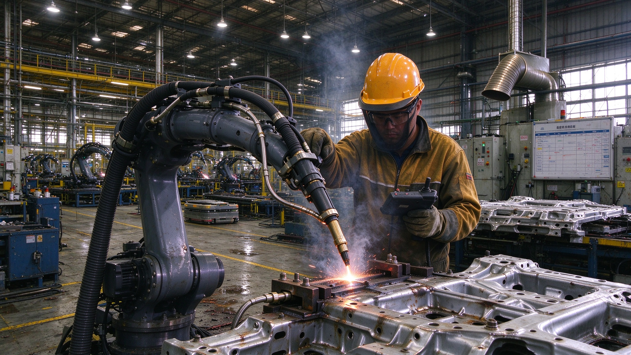
Corporate Advantages
Why Choose hivekiontech
In‑house Manufacturing
Modern R&D and Production Base
Global Logistics
Safe Worldwide Delivery
Worry‑free After‑sales
Full‑life‑cycle Services
Ready to start the cooperation?
Contact our professional team for customized equipment solutions.
Consult now